
Apparatus comprising a payload ejection mechanism

a technology of ejection mechanism and payload, which is applied in the direction of transportation and packaging, weapons, and cosmonautic vehicles, etc., can solve the problems of capsule-deployed payloads being particularly difficult to separate, damage the payload, and the wings being damaged during deployment, so as to reduce the risks of capsule-deployed payloads

Active Publication Date: 2010-07-27
LOCKHEED MARTIN CORP
View PDF10 Cites 17 Cited by
  • Summary
  • Abstract
  • Description
  • Claims
  • Application Information

AI Technical Summary

Benefits of technology

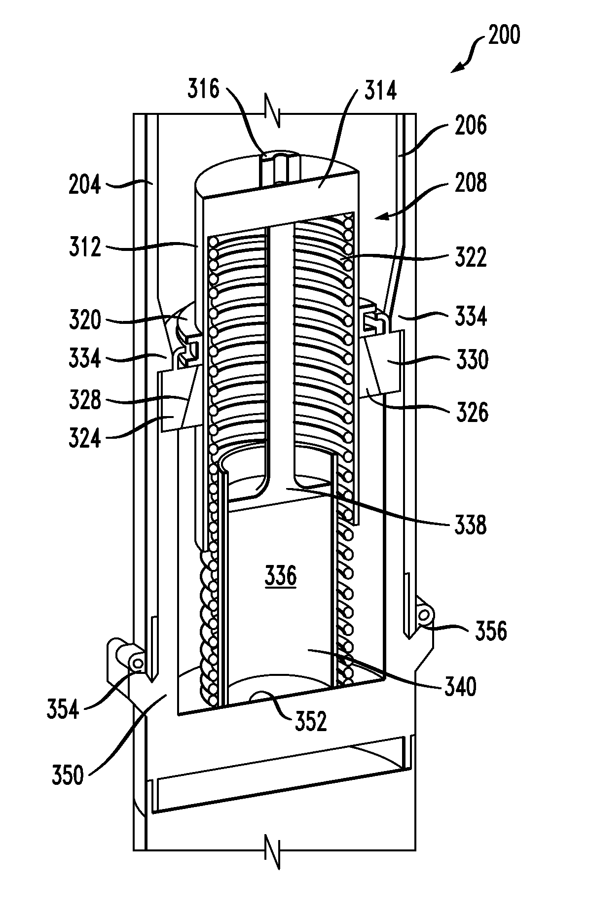
[0010]The present invention provides a combined shock absorption and payload ejection mechanism that reduces the risks to capsule-deployed payloads.
[0011]In accordance with the illustrative embodiment of the invention, the combined mechanism is disposed within a launch capsule. The mechanism is capable of reducing the shock that a payload would otherwise be exposed to upon launch and is also capable of increasing the separation distance between the payload and capsule upon deployment faster than in the prior art.
[0013]The payload is disposed on the movable housing. Due to the rapid acceleration of the capsule upon launch, the movable housing moves “downward.” Since both the resilient member and the piston are operably coupled to the housing, the downward movement of the movable housing compresses the resilient member and results in further insertion of the piston into the cylinder. The former action stores energy (as potential energy in the compressed spring) and the latter action results in damping that provides shock isolation for the payload.
[0014]A locking mechanism maintains the compression of the resilient member until the capsule opens to deploy the payload. As the capsule opens, a restraint decouples from the locking mechanism and permits the resilient member to expand. Expansion of the resilient member causes the movable housing to move. Since the payload is disposed on the movable housing, it is propelled forward, such that the separation distance between the payload and the capsule increases more quickly than in the absence of payload ejection mechanism.

Problems solved by technology

This debris can damage the payload.
If the payload doesn't rapidly clear the capsule, the wings can be damaged during deployment.
Payload separation can be particularly problematic during low-speed deployments, wherein relatively diminished aerodynamic forces are available to brake the capsule.
In such cases, the payload and capsule might not separate enough to permit safe wing deployment or for the payload to clear debris, etc.

Method used


Image

  • Apparatus comprising a payload ejection mechanism
  • Apparatus comprising a payload ejection mechanism
  • Apparatus comprising a payload ejection mechanism

Examples


Embodiment Construction

[0031]The following terms are defined for use in this specification, including the appended claims:[0032]Operatively-coupled means that the operation, action, movement, etc. of one object affects another object. For example, consider a spring that abuts a plate.

[0033]When the plate is moved, downward, the spring is compressed. The plate and the spring are considered to be “operatively-coupled.” Operatively-coupled devices can be coupled through any medium (e.g., semiconductor, air, vacuum, water, copper, optical fiber, etc.) and involve any type of force. Consequently, operatively-coupled objects can be electrically-coupled, hydraulically-coupled, magnetically-coupled, mechanically-coupled, optically-coupled, pneumatically-coupled, physically-coupled, thermally-coupled, etc.[0034]Resilient and its inflected forms, refers to a tendency to return to a reference or original state (e.g., shape, position, etc.). Resilience, as a characteristic of a member, can arise in several ways. In s...


PUM


Abstract

An apparatus that provides shock absorption and ejection for a payload that is to be deployed from a launch capsule is disclosed. The payload ejection mechanism comprises a movable housing that houses a resilient member and a shock-damping system. The rapid acceleration of the capsule upon launch causes the movable housing to move, which compresses the resilient member, thereby storing energy. Movement of the housing also provides shock damping behavior. A locking mechanism maintains the compression of the resilient member until the capsule opens to deploy the payload. As the capsule opens, a restraint decouples from the locking mechanism and permits the resilient member to expand. Expansion of the resilient member causes the movable housing to move, thereby propelling the payload away from the capsule.

Description

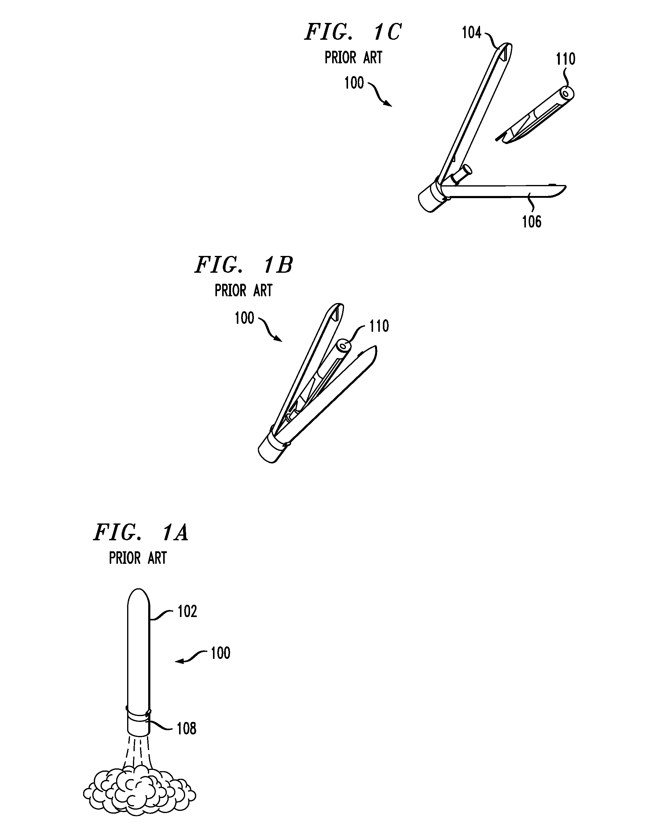
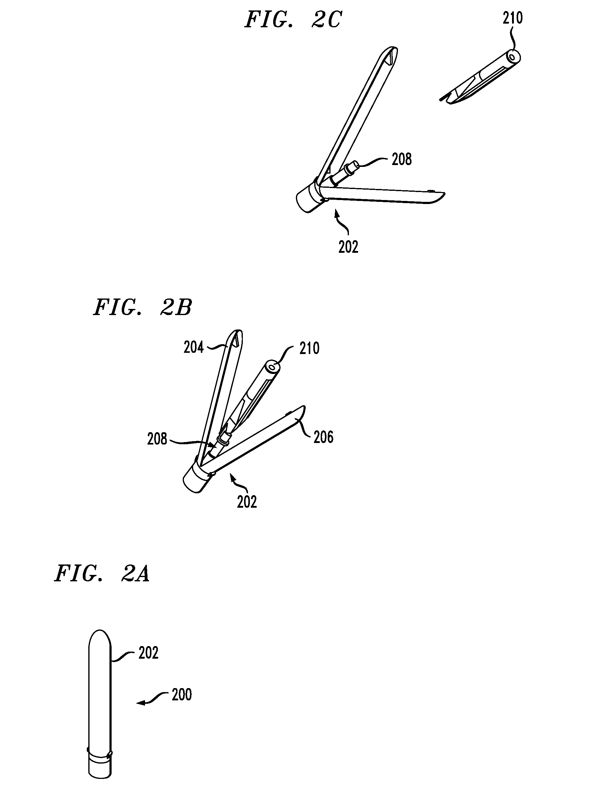
FIELD OF THE INVENTION[0001]The present invention relates to munitions or launch capsules and, more particularly, a payload ejection mechanism for use in conjunction with such capsules.BACKGROUND OF THE INVENTION[0002]Some launch capsules carry payloads that are intended to be separated from the capsule in flight. This familiar process of deploying munitions or the like from a capsule is depicted in FIGS. 1A through 1C.[0003]FIG. 1A depicts the launch of capsule 100. In this illustration, capsule 100 contains booster 108, which provides the thrust required for launch. In this example, the payload is an unmanned aerial vehicle, usually referred to as a “UAV.” The UAV is not visible in FIG. 1A since it is within shell 102[0004]At some predetermined altitude or time, shell 102 of capsule 100 opens in preparation for releasing UAV 110, as depicted in FIG. 1B. Typically, explosive bolts or similar mechanisms are used to open the capsule. As the capsule opens, UAV 110 is released from lau...

Claims


Application Information

Patent Timeline
IPC IPC(8): F42B12/58
CPCB64G1/641F42B12/58B64C2201/088B64G1/6425B64U70/80
Inventor GAIGLER, RANDY L.
Owner LOCKHEED MARTIN CORP
Learn More