
Vacuum valve

a vacuum valve and valve body technology, applied in the field of vacuum valves, can solve problems such as relative large construction

Inactive Publication Date: 2010-07-27
VAT HLDG AG
View PDF12 Cites 35 Cited by
  • Summary
  • Abstract
  • Description
  • Claims
  • Application Information

AI Technical Summary

Benefits of technology

This design achieves a simple, economical, and space-saving construction with high torsional rigidity and allows for precise positioning detection, enabling a reliable and efficient vacuum valve operation without valve rod bending.

Problems solved by technology

This construction is relatively complicated, and therefore costly, and results in a relatively large construction.

Method used


Image

  • Vacuum valve
  • Vacuum valve
  • Vacuum valve

Examples


Embodiment Construction

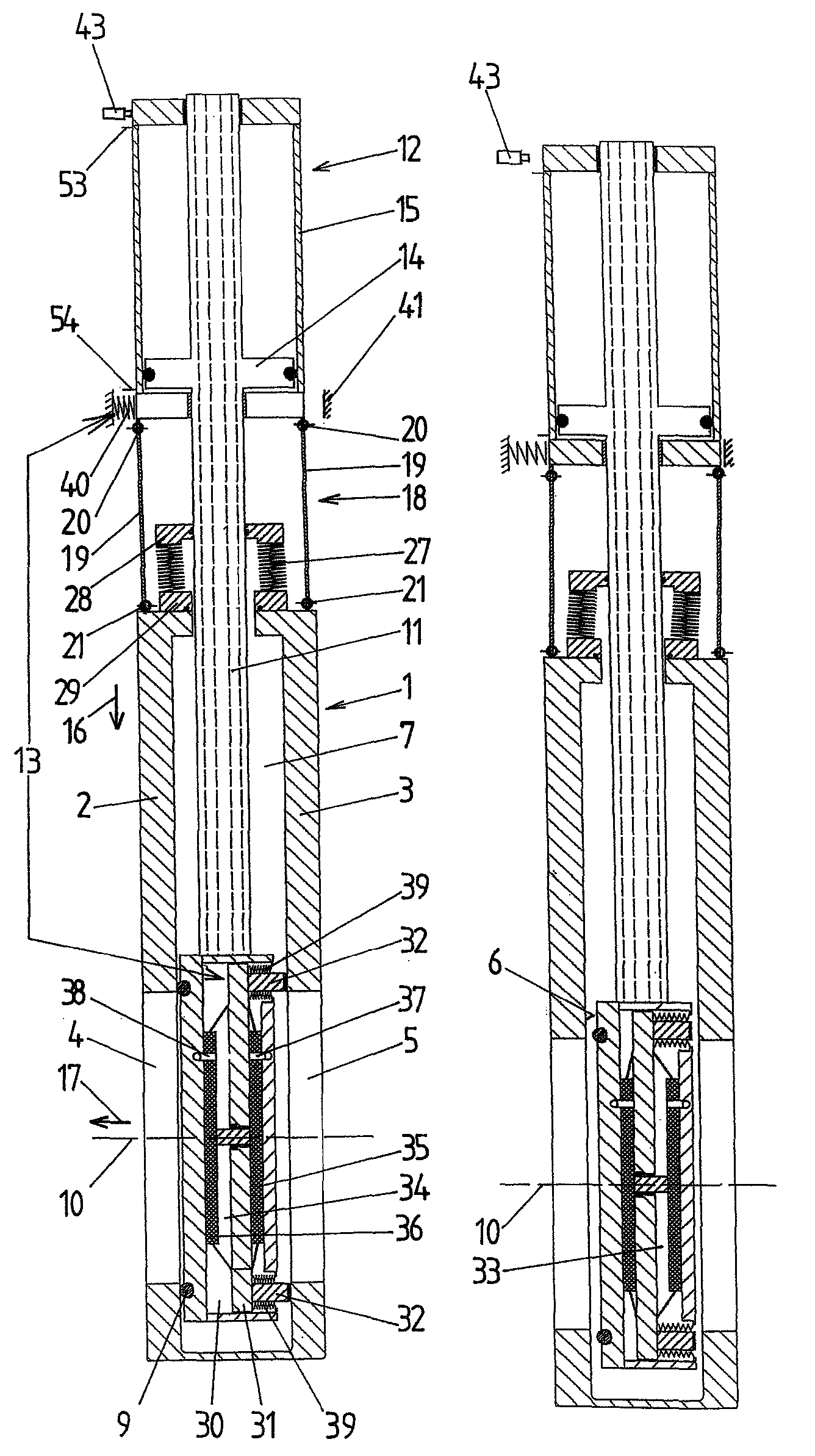
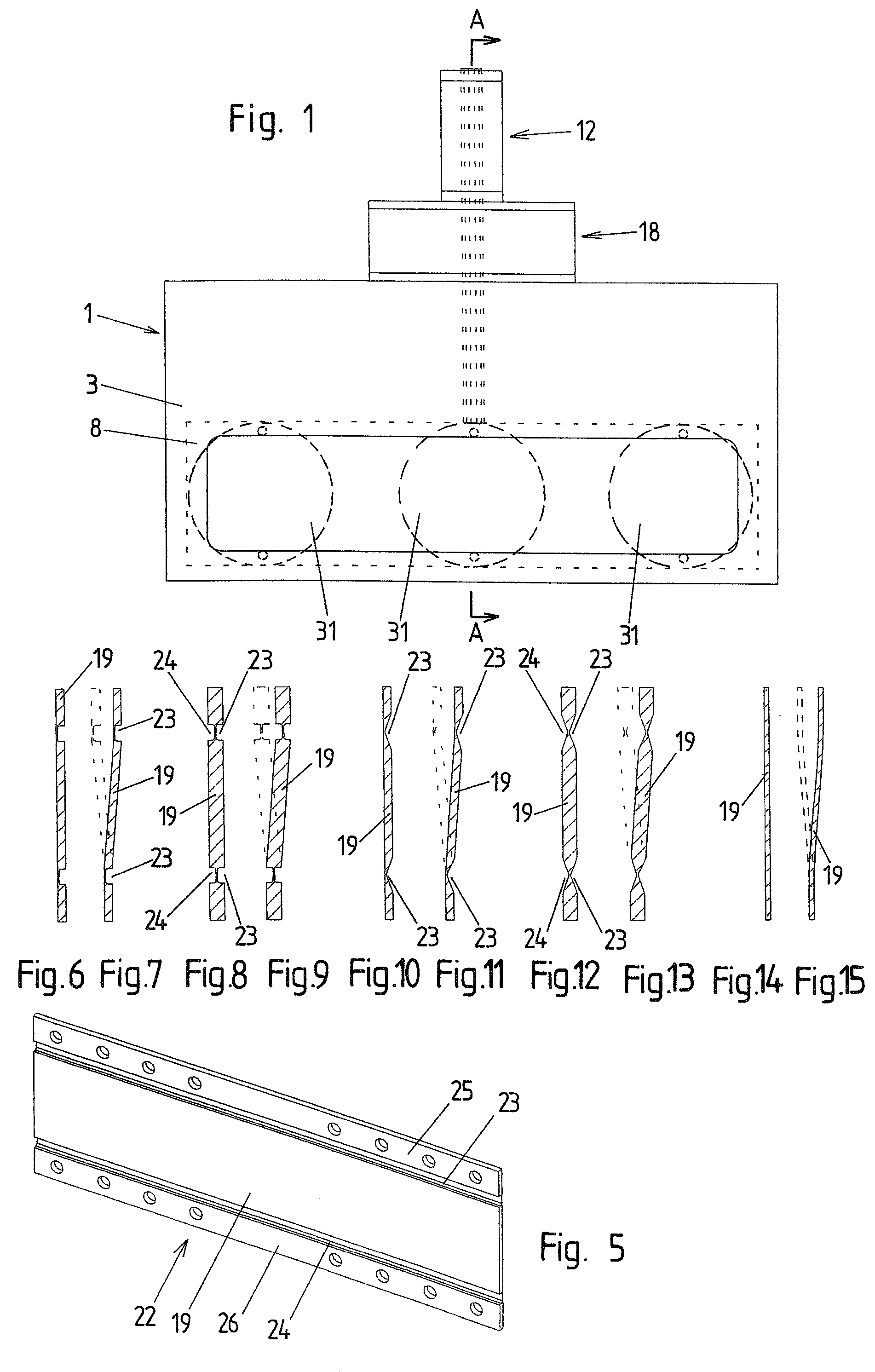
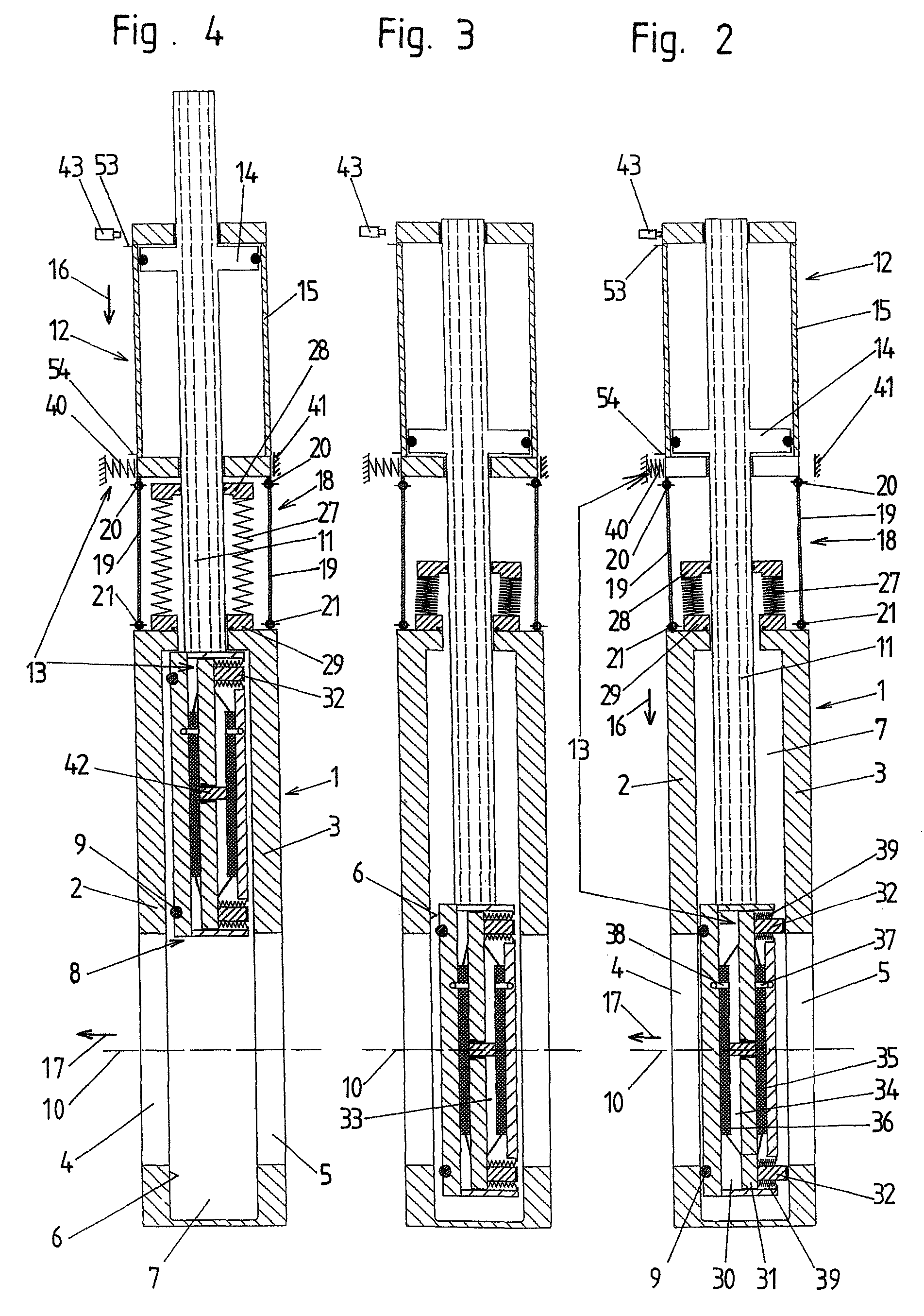
[0039]A first embodiment example of the invention is shown schematically in FIGS. 1 to 7. The vacuum valve has a valve body 1 which is constructed in the form of a housing in the present embodiment example. Opposite walls 2, 3 are penetrated by an inlet opening, which forms a valve opening 4, and by an outlet opening 5. The valve opening 4 is surrounded by a valve seat 6 which is formed by a sealing surface at the inner side of the wall 2.

[0040]In the present embodiment example, the longitudinal axis 10 of the valve opening and the longitudinal axis of the outlet opening 5 coincide in a preferred manner.

[0041]A valve plate 8 is arranged in the interior space 7 of the valve body 1 which forms a vacuum area of the vacuum valve. In the closed position of the valve plate 8, the valve plate 8 is pressed against the valve seat 6, and a seal 9 of the valve plate contacts the valve seat 6.

[0042]For example, the seal 9 could also be arranged at the valve seat 6 and a sealing surface could be...


PUM


Abstract

A vacuum valve comprises a valve body with a valve opening, a valve plate which is adjustable from an open position, in which it releases the valve opening, to an intermediate position, in which it covers the valve opening but is lifted from the valve seat, into a closed position in which it contacts the valve seat, and from the closed position to the intermediate position into the open position, a valve rod carrying the valve plate, a transverse drive unit by which the valve plate can be displaced in a transverse adjusting direction extending transverse to the longitudinal axis of the valve opening, a longitudinal drive unit by which the valve plate can be displaced in a longitudinal adjusting direction extending parallel to the longitudinal axis of the valve opening and opposite the longitudinal adjusting direction, and a guide device by which the transverse drive unit is guided so as to be displaceable relative to the valve body parallel to the longitudinal adjusting direction. The transverse drive unit is displaced relative to the valve body parallel to the longitudinal adjusting direction when the valve plate is adjusted from its intermediate position to its closed position and from its closed position to its intermediate position.

Description

CROSS-REFERENCE TO RELATED APPLICATION[0001]This application claims priority of Austrian Application No. A 1225 / 2006, filed Jul. 19, 2006, the complete disclosure of which is hereby incorporated by reference.BACKGROUND OF THE INVENTION[0002]a) Field of the Invention[0003]The invention is directed to a vacuum valve comprising a valve body with a valve opening having a longitudinal axis and a valve seat surrounding the valve opening, a valve plate which is adjustable from an open position, in which it releases the valve opening, to an intermediate position, in which it covers the valve opening but is lifted from the valve seat, into a closed position in which it contacts the valve seat, and from the closed position to the intermediate position into the open position, a valve rod carrying the valve plate, a transverse drive unit by means of which the valve plate can be displaced in a transverse adjusting direction extending transverse to the longitudinal axis of the valve opening from ...

Claims


Application Information

Patent Timeline
Patent Type & Authority Patents(United States)
IPC IPC(8): F16K25/00
CPCF16K3/18F16K51/02F16K3/314F16K31/122
Inventor SCHOEN, MATHIASHENRY, DIDIER
Owner VAT HLDG AG
Learn More