Two-dimensional lattice calibrating device, two-dimensional lattice calibrating method, two-dimensional lattice calibrating program and recording medium

a calibrating device and lattice technology, applied in the field of two-dimensional calibrating devices, can solve the problems of impracticality of inverse method calibration, grid plate (an artifact for vision measuring machines) cannot be highly calibrated by inverse method, and the difficulty of producing highly accurate artifacts, etc., to achieve the effect of easy chang

Active Publication Date: 2010-07-27
MITUTOYO CORP
View PDF7 Cites 6 Cited by
  • Summary
  • Abstract
  • Description
  • Claims
  • Application Information

AI Technical Summary

Benefits of technology

[0012]In the above aspect of the invention, the coordinate relational equation may include: an origin error An that is a deviation of an origin and a setting rotation error On as setting errors that are different per each of measurements under the respective measurement dispositions n; and a squareness error a of the artifact coordinate system and deviations δξ, δζ from the designed value as errors that are common to each of the measurements, the least-squares line equation may include a first conditional equation for minimizing average values of values adding the designed value and the deviation and a second conditional equation for minimizing averages of the deviations δξ, δζ, and the simultaneous-equations calculating unit may correct the designed value based on the squareness error α of the artifact coordinate system calculated by the simultaneous-equations calculating unit and the deviations δξ, δζ to repeatedly calculate the least-squares line.
[0013]According to the above arrangement, the coordinate relational equation can define the setting error independently from the deviation. Further, since the simultaneous-equations calculating unit repeatedly calculates the least-squares line to be the coordinate axes of the artifact coordinates, so that the deviation independent of the setting error and the measurement error can be accurately calculated.
[0019]According to the above arrangement, the same advantages and effect as the above two-dimensional lattice calibrating device can be obtained.
[0038]Accordingly, since all of the simultaneous equations are integrally calculated without solving a normal equation, the variables can be calculated with equal accuracy and the accuracy of calculation for solving the simultaneous equations can be improved as a whole.
[0041]Further, since the program is constructed so that the respective functions are achieved by the computer, the parameter for each process can be easily changed in accordance with input from an input means and predetermined measurement mode.

Problems solved by technology

However, it accompanies a great difficulty to produce a highly accurate artifact.
Accordingly, when it is difficult for an artifact to be measured from a backside, calibration using the inverse method is impractical.
For instance, a grid plate (an artifact for vision measuring machine) cannot be highly calibrated by the inverse method, since the condition varies between top-side measurement and backside measurement of the grid plate.

Method used


Image

  • Two-dimensional lattice calibrating device, two-dimensional lattice calibrating method, two-dimensional lattice calibrating program and recording medium
  • Two-dimensional lattice calibrating device, two-dimensional lattice calibrating method, two-dimensional lattice calibrating program and recording medium
  • Two-dimensional lattice calibrating device, two-dimensional lattice calibrating method, two-dimensional lattice calibrating program and recording medium

Examples


example

[0183]Next, an Example of the two-dimensional lattice calibrating device and the like of the present invention will be described below.

[0184]In this Example, in addition to the features of the above-described embodiment, the error ej of the measuring unit and the squareness error β of the measurement coordinates are simultaneously solved.

[0185]Initially, the terms used in the present Example will be defined as follows:

(1) Number

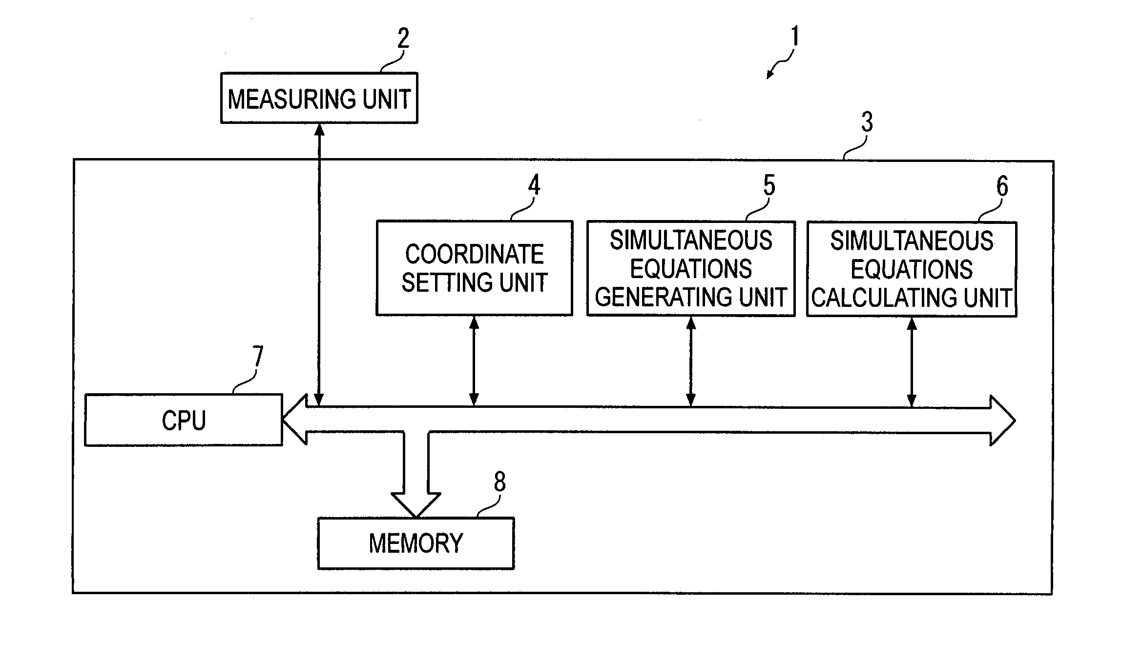
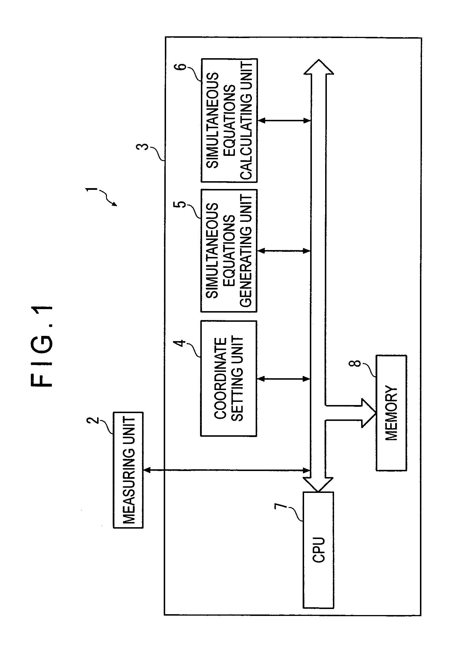
[0186]Measurement number n: the number of the measurement disposition (each of the measurements)

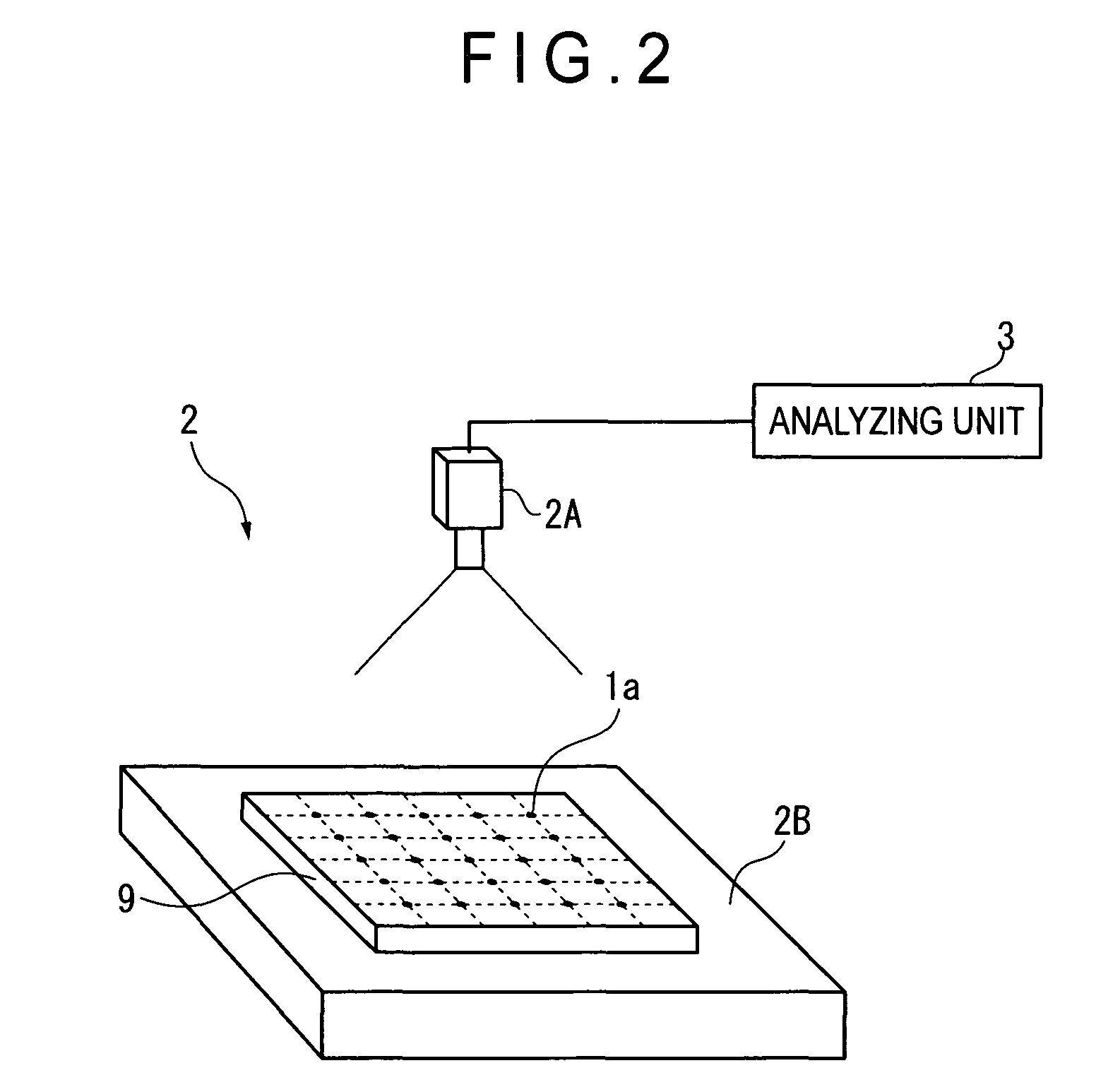
[0187]Mark number i: the number of each of the marks of the artifact (e.g. a square lattice).

[0188]Measurement range number j: the number of each of the measurement ranges (e.g. a measurement grid) of the measuring unit

(2) Coordinates, Coordinates Axis and Coordinate Value

[0189](2.1) Nominal Coordinates

[0190]Nominal coordinates: coordinates for defining the artifact coordinates and the measurement coordinates, which have two axes of x0-axis and y0-axis that pass an...


PUM


Abstract

A two-dimensional lattice calibrating device includes: a measuring unit that measures respective positions of marks for each of a plurality of measurement dispositions; a simultaneous-equations generating unit that generates simultaneous equations for acquiring deviations of the plurality of marks using a coordinate relational equation and a least-squares conditional equation that sets least-squares lines that minimize the deviation of actual position of the marks based on measurement values as coordinate axes of artifact coordinates; and a simultaneous-equations calculating unit that solves the derived simultaneous equations.

Description

BACKGROUND OF THE INVENTION[0001]1. Field of the Invention[0002]The present invention relates to a two-dimensional calibrating device. More specifically, it relates to a two-dimensional lattice calibrating device that calibrates a mark position of an artifact (e.g. square lattice) as a standard gauge. The present invention also relates to a two-dimensional lattice calibrating method, two-dimensional lattice calibrating program and a recording medium storing the program.[0003]2. Description of Related Art[0004]Conventionally, block-shaped and plate-shaped standard gauges have been used for calibrating a precise measuring instrument. Among such standard gauges, those having square-lattice marks (including measuring point, center of a ball and the like) such as a ball plate and a grid plate are called as artifacts, which are used as a standard mainly for calibrating a coordinate measuring machine and a vision measuring machine. Accordingly, the position of the marks has to be sufficien...

Claims


Application Information

Patent Timeline
Patent Type & Authority Patents(United States)
IPC IPC(8): G01P21/00
CPCG01B21/042
Inventor NARA, MASAYUKIABBE, MAKOTO
Owner MITUTOYO CORP
Why Eureka
Try Eureka