Drain-clearing device

a technology of drain clearing device and plunger, which is applied in the direction of sewer cleaning, hollow article cleaning, catheter cleaning, etc., can solve the problems of user facing the disadvantages of obtaining and using a plumbing snake, and the use of a plunger alone is insufficient to clear obstructions, etc., to prevent water spillage, convenient use, and economical manufacturing

Active Publication Date: 2010-08-03
SAPIA FRANCO
View PDF23 Cites 10 Cited by
  • Summary
  • Abstract
  • Description
  • Claims
  • Application Information

AI Technical Summary

Benefits of technology

[0006]Further, a snaking member is positioned in the first and second hollow tubes and movement of the hollow tubes between the extended and retracted configurations causing the snaking member to move between storing and operating configurations, respectively. A crank handle is coupled to the second end of the second hollow tube and is coupled to the snaking member for selective rotational movement thereof. In addition, the drain clearing device includes a plug for selectively sealing an inner area of said first hollow tube from an inner area of said plunger head, whereby to eliminate water spillage issues.
[0010]A further object of this invention is to provide a drain clearing device, as aforesaid, having a plug for sealing an inner area of the first tube and preventing water spillage.
[0011]A still further object of this invention is to provide a drain clearing device, as aforesaid, that is easy to use and economical to manufacture.

Problems solved by technology

However, there are times when use of the plunger alone is insufficient to clear the obstruction.
If unsuccessful, the user faces the disadvantages of obtaining and using a plumbing snake.
Although assumably effective for their intended purposes, the existing devices do not seal the snaking device within the handle of the plunger so as to eliminate water spillage issues, provide a two-part extended handle configuration, or have a convenient crank handle for operation of the snaking device.

Method used


Image

  • Drain-clearing device
  • Drain-clearing device
  • Drain-clearing device

Examples


Embodiment Construction

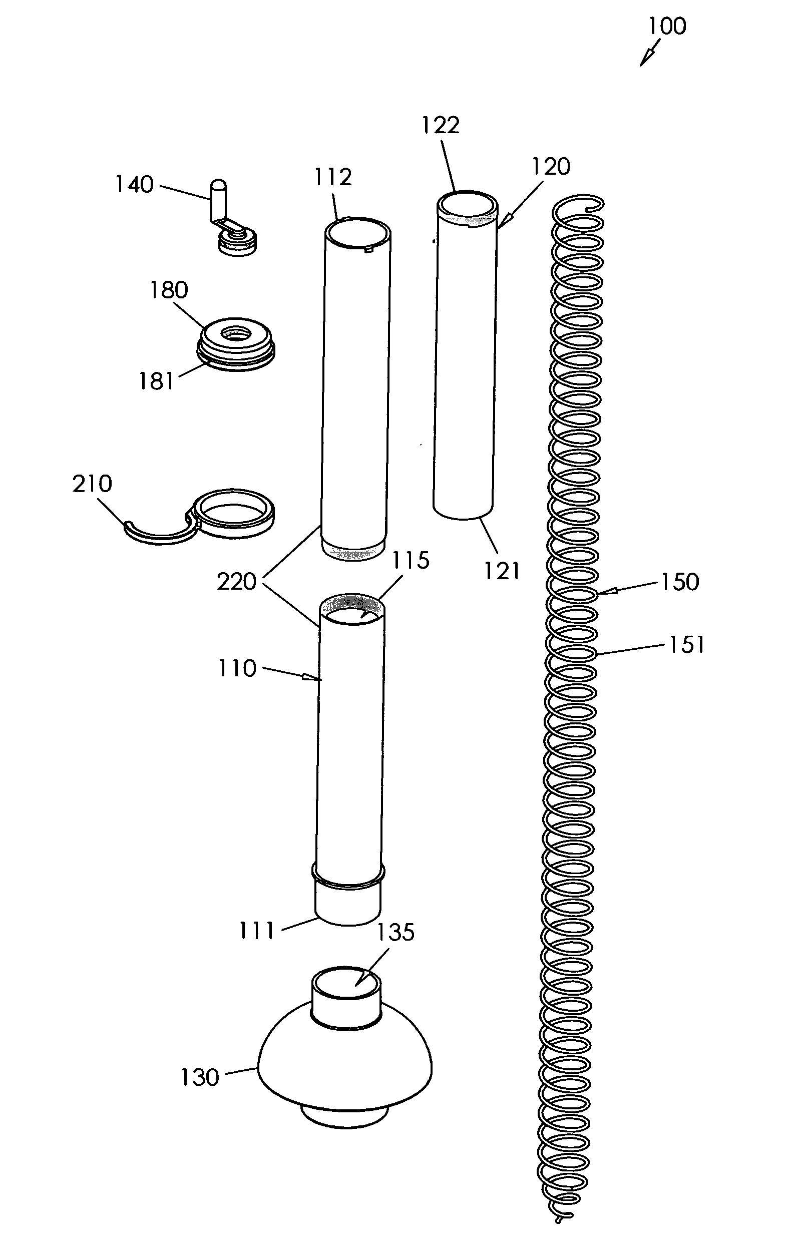
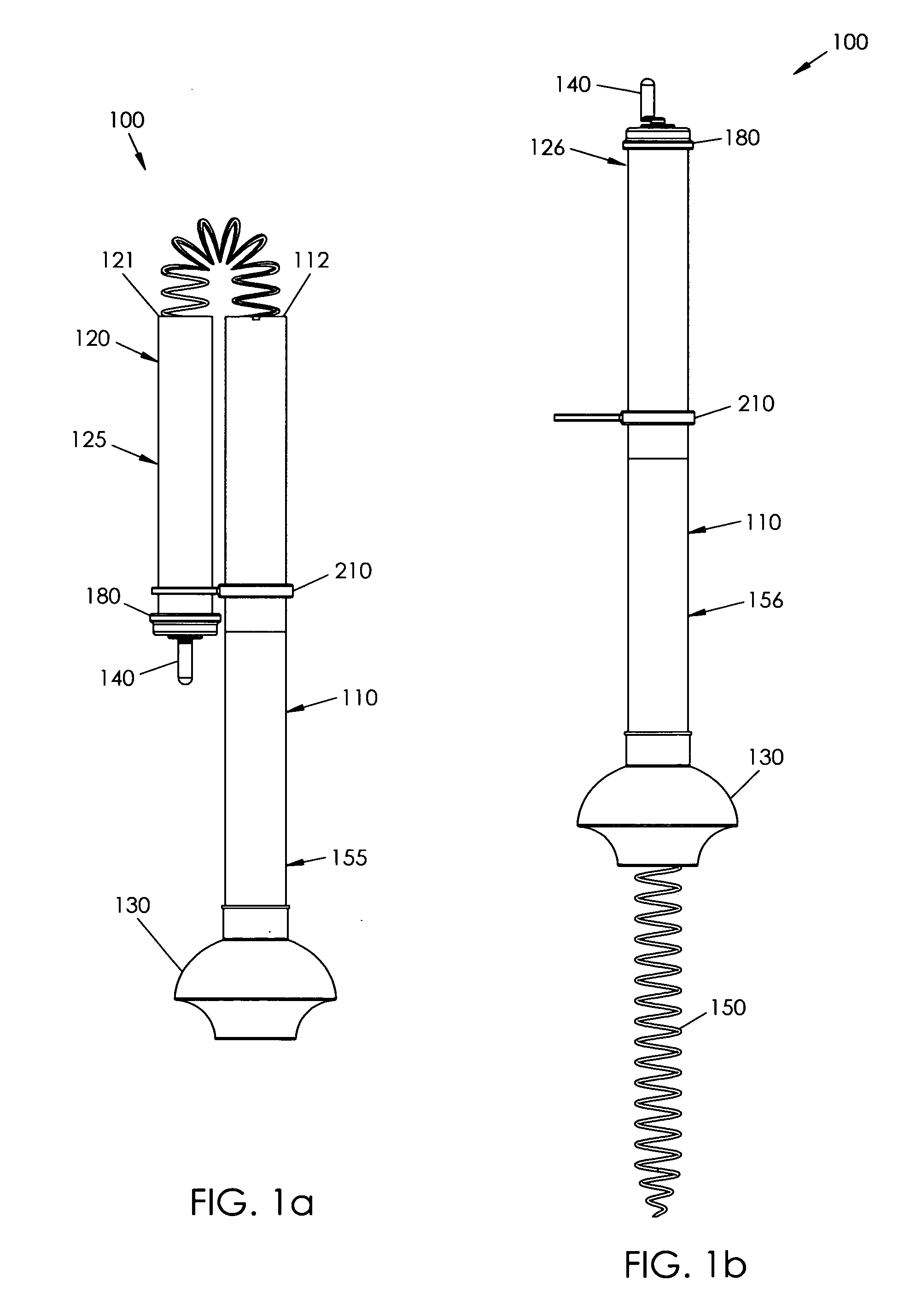
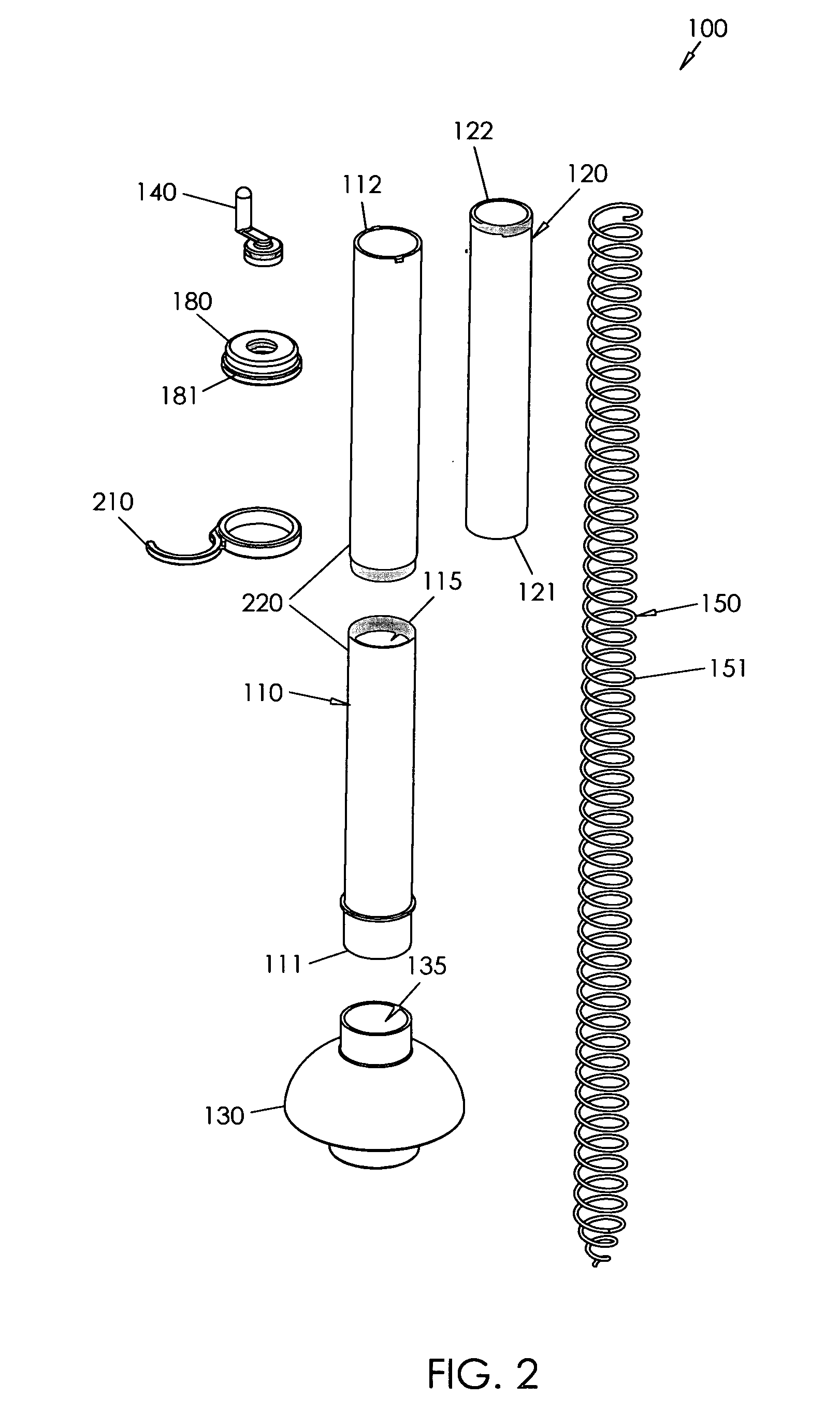
[0023]A drain-clearing device 100 particularly for use with a toilet or sink according to the present invention will now be described in detail with reference to FIGS. 1a through 4c of the accompanying drawings. More particularly, a drain-clearing device 100 according to the current invention includes a first hollow tube 110, a second hollow tube 120, a plunger head 130, a crank handle 140, and a snaking member 150.

[0024]The first hollow tube 110 has opposed first and second ends 111, 112 and defines an inner area 115 (FIGS. 1 and 2). The second hollow tube 120 has opposed first and second ends 121, 122. The first end 121 of the second hollow tube 120 is operatively coupled to the second end 112 of the first hollow tube 110 so that the first hollow tube 110 and the second hollow tube 120 are configured for telescoping movement between an extended configuration 125 (FIGS. 1a and 3a) and a retracted configuration 126 (FIGS. 1b and 4a). The second hollow tube 120 may have a smaller dia...


PUM


Abstract

A drain clearing device includes a first hollow tube having opposed first and second ends and a plunger head coupled to the first end. A second hollow tube includes a first end operatively coupled to the first end of the first tube, the first and second tubes being configured for telescoping movement between extended and retracted configurations. A snaking member is situated in the first and second tubes for movement between storing and operating configurations when the tubes are moved between extended and retracted configurations, respectively. A crank handle connected to the snaking member enables a user to rotate and extend the snake as needed. A plug is included for separating an inner tube area from an inner area of the plunger head and to prevent water spillage from the tubes.

Description

BACKGROUND OF THE INVENTION[0001]The present device relates generally to plumbing accessory devices and, more particularly, to a drain clearing device having a plunger and snaking device integrated in a dual tube arrangement.[0002]A plunger is a plumbing accessory that is traditionally used to unclog a toilet that has become obstructed. The plunger includes a semi-flexible head with which to apply suction to the trap of the toilet. However, there are times when use of the plunger alone is insufficient to clear the obstruction. In such a case, a plumbing snake may be utilized. A plumbing snake typically utilizes an elongate, flexible metal wire or cord that may be extended into or even through the toilet trap to forcefully dislodge or break up the obstruction.[0003]A plunger is usually the first plumbing accessory that is employed when an obstruction is experienced as the plunger is usually sufficient to remedy the problem. If unsuccessful, the user faces the disadvantages of obtaini...

Claims


Application Information

Patent Timeline
Patent Type & Authority Patents(United States)
IPC IPC(8): E03D11/00
CPCE03C1/302E03F9/005
Inventor SAPIA, FRANCO
Owner SAPIA FRANCO
Why Eureka
Try Eureka