Cooking apparatus and method for controlling the same

a technology of cooking apparatus and control method, which is applied in the field of cooking apparatus, can solve the problems of long cooking time, excessive consumption of electric power, and limit the uniform movement of hot air in the cooking chamber, and achieve the effect of uniform temperature distribution

Inactive Publication Date: 2010-08-03
SAMSUNG ELECTRONICS CO LTD
View PDF43 Cites 86 Cited by
  • Summary
  • Abstract
  • Description
  • Claims
  • Application Information

AI Technical Summary

Benefits of technology

[0019]It is another aspect of the invention to provide a cooking apparatus and a method for controlling the same, wherein hot air is fed into a predetermined local region of a cooking space, or the overall cooking space can achieve a uniform temperature distribution.
[0037]The control unit may control one of the upper and lower air-direction regulators, to prevent the hot air from being discharged into one of the first and second cooking chambers, to which no cooking command is inputted, when a cooking command is inputted to the other cooking chamber.

Problems solved by technology

However, since the duct to feed the hot air into the cooking chamber is installed to the cooking chamber at a fixed position, the hot air creates a confined air stream, resulting in a limit to the uniform movement of the hot air in the cooking chamber.
Accordingly, since the overall cooking chamber should be heated even when only a small amount of food is cooked, there is a problem of a long cooking time and excessive consumption of electric power.
Although the invention disclosed in the second publication can solve problems of the first publication to some extent, it needs to provide a heater and a blowing fan in each of the first and second cooking chambers separated from each other by the partition, resulting in very high manufacturing costs.

Method used


Image

  • Cooking apparatus and method for controlling the same
  • Cooking apparatus and method for controlling the same
  • Cooking apparatus and method for controlling the same

Examples


Embodiment Construction

[0055]Reference will now be made in detail to exemplary embodiments of the present invention, examples of which are illustrated in the accompanying drawings, wherein like reference numerals refer to like elements throughout. The embodiments are described below to explain the present invention by referring to the figures.

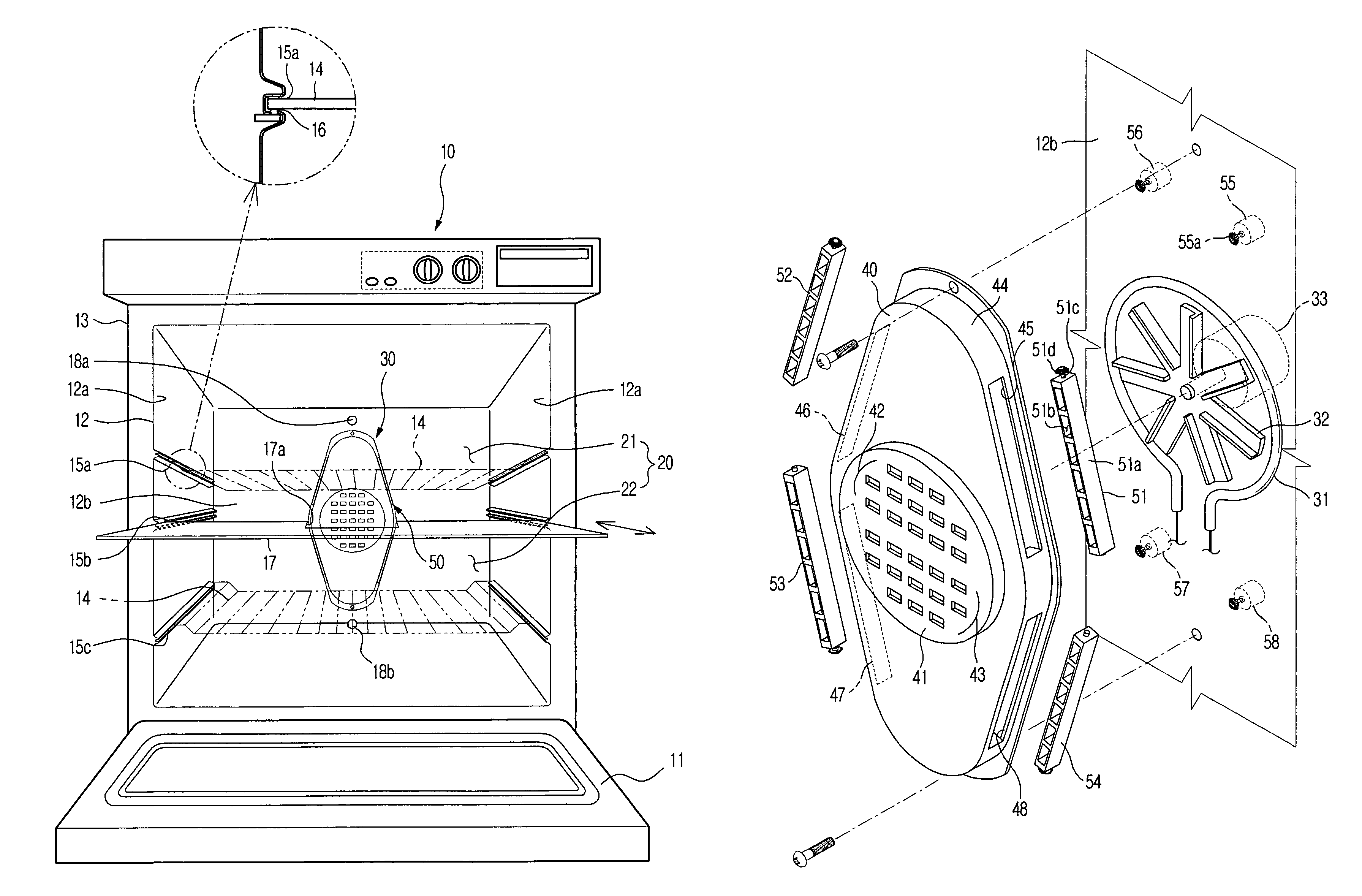
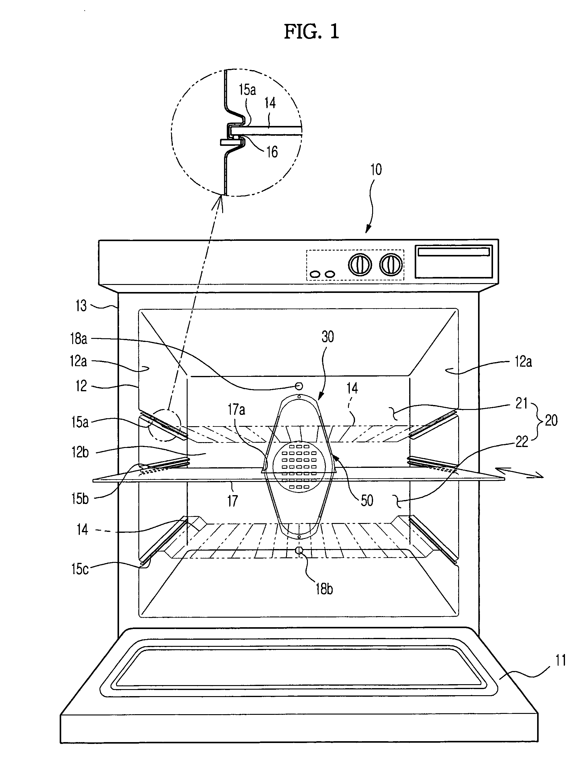
[0056]FIG. 1 is a perspective view illustrating the schematic configuration of a cooking apparatus according to an exemplary embodiment of the present invention.

[0057]The cooking apparatus according to the present invention, as shown in FIG. 1, includes a body 10 having an open front surface and defining a cooking chamber 20 therein, a door 11 pivotally rotatably provided at the front surface of the body 10 to open or close the cooking chamber 20, a hot-air feeder 30 to feed hot air into the cooking chamber 20, and an air-direction regulator 50 to regulate the direction of the hot air fed from the hot-air feeder 30.

[0058]The body 10 includes an inner case 12 defining...


PUM


Abstract

A cooking apparatus to change the direction of hot air to be fed into a cooking chamber. The cooking apparatus includes a cooking chamber, a hot-air feeder to feed hot air into the cooking chamber, and an air-direction regulator to change a direction of the hot air fed from the hot-air feeder.

Description

CROSS-REFERENCE TO RELATED APPLICATIONS[0001]This application claims the benefit of Korean Patent Application No. 2007-0101205, filed on Oct. 9, 2007 in the Korean Intellectual Property Office, the disclosure of which is incorporated herein by reference.BACKGROUND[0002]1. Field[0003]The present invention relates to a cooking apparatus and a method for controlling the same, and, more particularly, to a cooking apparatus to cook an object to be cooked, etc. by use of a blowing fan, and a method for controlling the same.[0004]2. Description of the Related Art[0005]In general, a conventional convection type cooking apparatus includes a heater, an oven cavity providing a space in which food is cooked using heat emitted from the heater, a blowing fan disposed in the oven cavity to circulate air inside the oven cavity by convection, convection suction and discharge holes mainly provided at a rear surface of the cavity to suction or discharge the air circulated by rotations of the blowing f...

Claims


Application Information

Patent Timeline
Patent Type & Authority Patents(United States)
IPC IPC(8): A21B1/24A21B1/22A21B1/26A23L5/10
CPCF24C7/082F24C15/325F24C7/04F24C7/06
Inventor KIM, TAE WOOHONG, SEOK WEONSHON, JONG CHULLKIM, HYANG KIKIM, JEONG HAN
Owner SAMSUNG ELECTRONICS CO LTD
Why Eureka
Try Eureka