Conveyor chain support for feeder house

a feeder house and chain support technology, applied in the field of conveyors, can solve the problems of increased drive torque, increased chain wear and loss of lubrication through heating and evacuation, and increased chain wear and loss of lubrication, so as to reduce the harvesting operation speed, reduce the wear on the feeder house components, and reduce the effect of throughput control simple and effectiv

Active Publication Date: 2010-08-03
DEERE & CO
View PDF18 Cites 17 Cited by
  • Summary
  • Abstract
  • Description
  • Claims
  • Application Information

AI Technical Summary

Benefits of technology

[0006]It is an object of the present invention to provide a simple and effective throughput control system for an agricultural combine that reduces wear on the feeder house components without having to reduce the harvesting operation speed.
[0007]The present invention utilizes a pivoting mid-floor section located between the transverse drum and the transverse sprocket means. The pivoting mid-floor is an improvement over the previous fixed mid-floor devices in that the mid-floor can pivot or adjust when a large glut of material is being fed into the feeder house, thus reducing the friction on the chain, reducing the torque required to operate the system, and preventing the system slow downs that occurred in feeder house systems using a fixed mid-floor. Additionally, replaceable wear-resistant, low-friction wear pads can be affixed to the contact surfaces of the runners or guides of the mid-floor or to the underside of the slats to further extend wear life and reduce friction between the chain slats and mid-floor. The contact occurs between the wear pads and the conveyor parts, rather than between the chain components and the conveyor parts, reducing chain wear and friction heat.

Problems solved by technology

A surge in volume of crop material entering the feeder house from the harvesting mechanism can place a large amount of pressure on the conveyor chain assembly, forcing the chain against fixed portions of the feeder house, conveyor assembly, and / or mid-floor, resulting in increased friction on the chain, which can cause premature chain wear and loss of lubrication through heating and evacuation.
Additionally, the pressure on the chain can slow down the conveyor system in order to accommodate processing the volume of crop material, resulting in an increase in drive torque.
This change in processing speed causes additional wear on the chain and drive components, and can lead to inefficient processing of crop material.
In some situations, if a large volume of material becomes lodged in the feeder house, the system can stall, necessitating the system be shut down and the excess material removed.

Method used


Image

  • Conveyor chain support for feeder house
  • Conveyor chain support for feeder house
  • Conveyor chain support for feeder house

Examples


Embodiment Construction

[0017]In the discussion of the FIGURES the same reference numerals will be used throughout to refer to the same or similar components. In the interest of conciseness, various other components known to the art, such as crops, storage mechanisms and the like necessary for the operation of the invention, have not been shown or discussed, or are shown in block form.

[0018]In the following, numerous specific details are set forth to provide a thorough understanding of the present invention. However, it will be obvious to those skilled in the art that the present invention may be practiced without such specific details. Additionally, for the most part, details concerning harvester combine operation and the like have been omitted inasmuch as such details are not considered necessary to obtain a complete understanding of the present invention, and are considered to be within the knowledge of persons of ordinary skill in the relevant art.

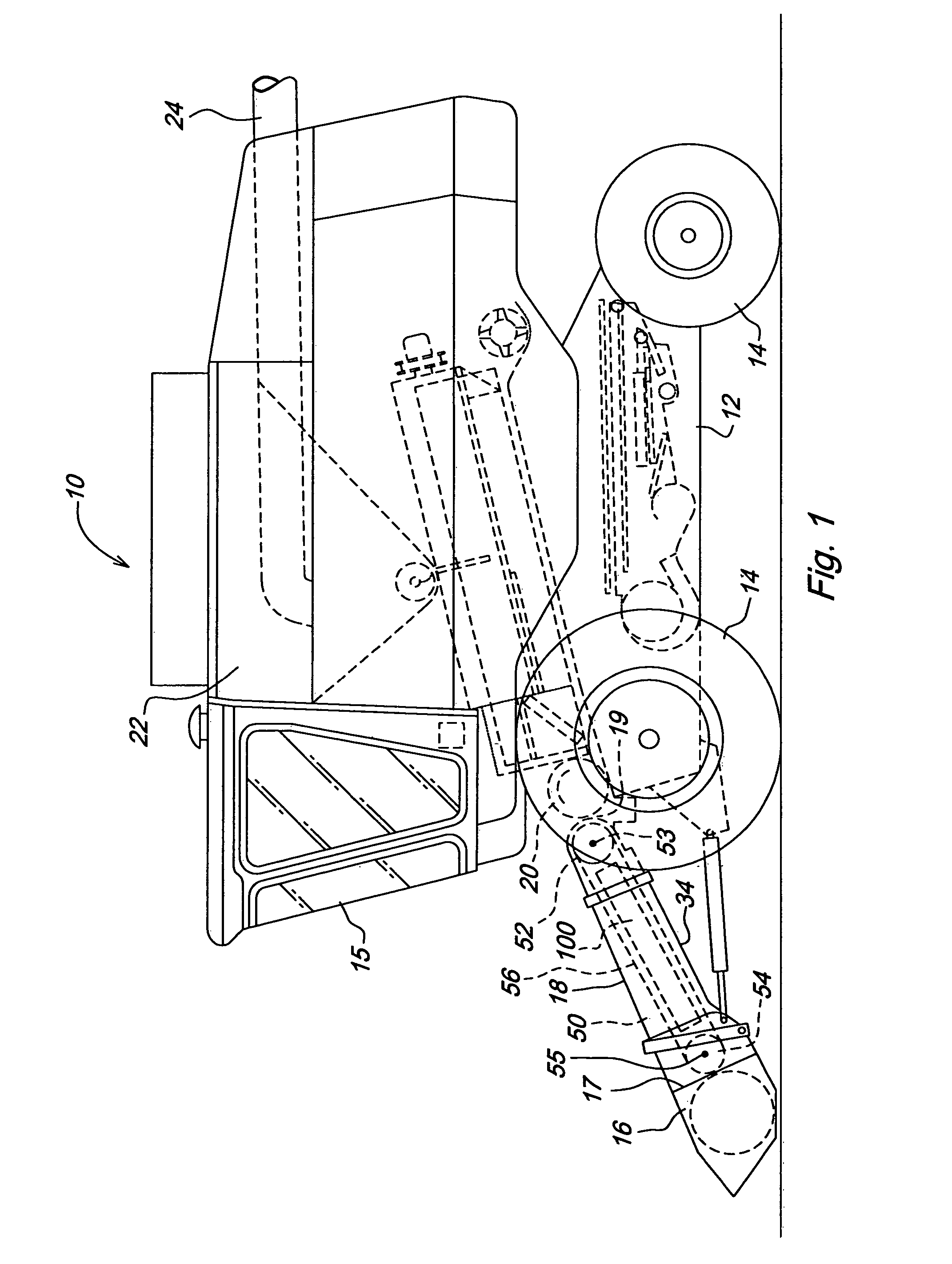
[0019]FIG. 1 shows a combine 10 used for harvesting agr...


PUM


Abstract

A pivoting mid-floor section for use in a feeder house in an agricultural combine is located between the transverse drum and the transverse sprocket means. The pivoting mid-floor can move or adjust when a large volume of crop material is fed into the feeder house, while providing support for the conveyor chain along substantially the entire length of travel between the transverse drum and sprocket means, thus reducing the friction on the chain, and preventing the system slow downs that occurred in feeder house systems using a fixed mid-floor. Additionally, replaceable wear-resistant surfaces can be affixed to the runners or guides of the mid-floor to further extend wear life and reduce friction between the chain slats and mid-floor. The friction occurs between the wear pads on the runners or guides and the chain slats, rather than between the chain components and the mid-floor.

Description

FIELD OF THE INVENTION[0001]This invention relates to a crop feeding conveyor for an agricultural harvesting machine, such as a combine or the like, more particularly to a type of conveyor known as a chain-and-slat type conveyor, and even more particularly to a portion of the support system for a chain-and-slat type conveyor known as the mid-floor.BACKGROUND OF THE INVENTION[0002]Combines are large self-propelled vehicles used for harvesting and threshing agricultural crop in a field. A combine operates by cutting or gathering crop standing in a field, and feeding the cut crop to a separator by means of a conveyor mechanism contained in a mechanism known as a feeder house. In the separator, grain is threshed, or beaten from the husk, stems, pods, or cobs, and then the threshed grain is separated from crop material other than grain. The cleaned grain is moved to a grain tank, and the crop material other than grain is generally distributed back out on the field behind the combine, or ...

Claims


Application Information

Patent Timeline
Patent Type & Authority Patents(United States)
IPC IPC(8): A01F12/00
CPCA01F12/10
Inventor RAMP, BENJAMIN EARLSCHRAEDER, JOHN ANTHONYPAYNE, MARK EDWARDFRANA-GUTHRIE, REBECCA ANNMELTON, MARK ALANHOGUE, JEFFREY WAYNE
Owner DEERE & CO
Why Eureka
Try Eureka