Coreless printed-circuit-board (PCB) transformers and operating techniques therefor

a technology of printed circuit board and transformer, which is applied in the incorporation of printed electric components, fixed transformers or mutual inductances, and inductances, etc. it can solve the problems that the commonly used ferrite rings cannot be used in the bourgeois society, and achieve the effect of reducing costs, ensuring stability and ensuring reliability

Inactive Publication Date: 2010-08-03
CITYU RES
View PDF18 Cites 18 Cited by
  • Summary
  • Abstract
  • Description
  • Claims
  • Application Information

AI Technical Summary

Benefits of technology

[0007]It is an object of the present invention therefore to provide a coreless PCB-based transformer. By eliminating the need for a transformer core at all, cost is reduced and the automated manufacture considerably simplified. It is also an object of the invention to provide means for controlling the operating frequency of such coreless PCB-based transformers and to provide optimal operating techniques for coreless PCB transformers (1) under minimum input power requirement (such as in a gate drive circuit for a power mosfet) and (2) under maximum energy efficiency (such as in a power converter).

Problems solved by technology

However, in Bourgeois a ferrite core is still required, and while Bourgeois has the advantage of avoiding the use of a manually wound transformer, commonly used ferrite rings cannot be used in Bourgeois because it is impossible to put ferrite rings through the PCB without breaking the rings.
Although Bourgeois makes some progress towards the desired reduced cost and increased automation, the advantage provided is limited by the requirement to provide a ferrite core and the need to use two core sets glued together.

Method used


Image

  • Coreless printed-circuit-board (PCB) transformers and operating techniques therefor
  • Coreless printed-circuit-board (PCB) transformers and operating techniques therefor
  • Coreless printed-circuit-board (PCB) transformers and operating techniques therefor

Examples


Embodiment Construction

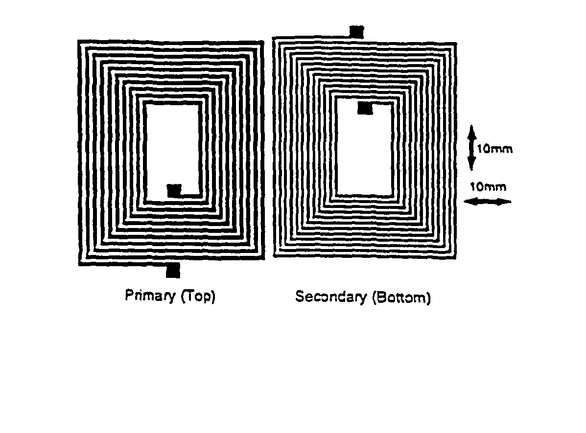
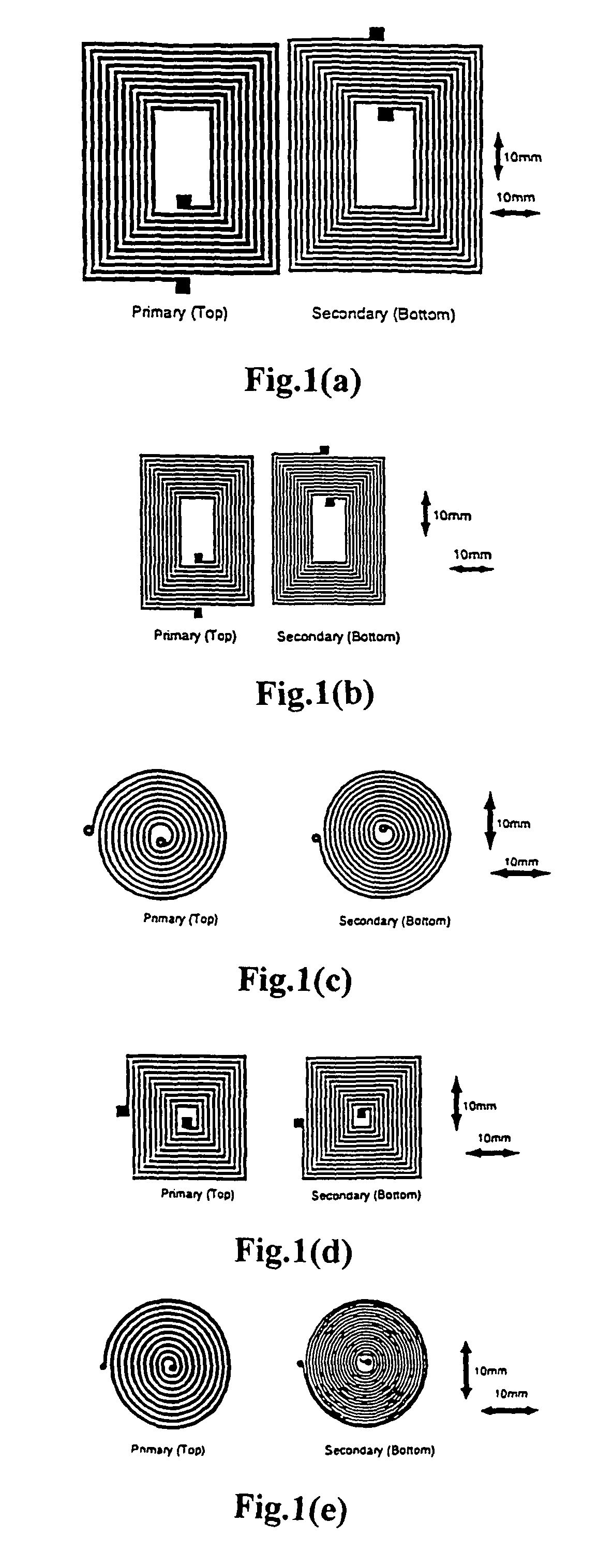
[0064]FIGS. 1(a)-(e) illustrate five transformers in accordance with embodiments of the invention. Each figure shows the primary and secondary “windings” side by side. In practice, of course, the primary and secondary windings are deposited by conventional PCB techniques on top and bottom sides of a PCB of a thickness of 1.54 mm. The primary and secondary windings are laid directly on opposite sides of the double-sided PCB in order to minimise the leakage inductances. The transformers of FIGS. 1(a)-(d) have 10 turns in the primary winding and 12 in the secondary winding. The additional two turns in the secondary winding are to compensate for the voltage drop. The transformer of FIG. 1(e) has 10 primary turns and 18 secondary turns. The dimensions of the transformers are schematically indicated in the Figures. The transformer of FIG. 1(a) corresponds to that of Bourgeois but with the ferrite core removed.

[0065]All five transformers of FIGS. 1(a)-(e) are capable of driving power devic...


PUM

PropertyMeasurementUnit
frequencyaaaaaaaaaa
frequencyaaaaaaaaaa
frequenciesaaaaaaaaaa

Abstract

Optimal operating techniques are disclosed for using coreless printed-circuit-board (PCB) transformers under (1) minimum input power conditions and (2) maximum energy efficiency conditions. The coreless PCB transformers should be operated at or near the ‘maximum impedance frequency’ (MIF) in order to reduce input power requirement. For maximum energy efficiency, the transformers should be at or near the “maximum efficiency frequency” (MEF) which is below the MIF. The operating principle has been confirmed by measurement and simulation. The proposed operating techniques can be applied to coreless PCB transformers in many circuits that have to meet stringent height requirements, for example to isolate the gates of power MOSFET and IGBT devices from the input power supply.

Description

[0001]This application is a Continuation of application Ser. No. 09 / 316,735, filed May 21, 1999, which is a Continuation-in-Part of application Ser. No. 09 / 018,871, filed Feb. 5, 1998, which applications are incorporated herein by reference.FIELD OF THE INVENTION[0002]This invention relates to PCB-based transformers, and in particular to coreless PCB-based transformers and to optimal operating techniques for such transformers.BACKGROUND OF THE INVENTION[0003]Transformers are commonly used for energy and signal transfer and for providing electrical isolation. Commonly used magnetic core-based transformers require a manual winding process, which not only increases the labour cost but also prohibits full automation of the circuits in the manufacturing process. This disadvantage has prompted research efforts on making planar transformer and / or inductor windings on printed circuit boards (PCBs).DESCRIPTION OF THE RELATED ART[0004]Recent research has been directed towards forming transfor...

Claims


Application Information

Patent Timeline
Patent Type & Authority Patents(United States)
IPC IPC(8): H01F5/00H01F17/00H01F19/04H05K1/16
CPCH01F17/0006H01F19/04H05K1/165H05K2201/10166
Inventor HUI, SHU YUEN RONTANG, SAI CHUN
Owner CITYU RES
Why Eureka
Try Eureka