
Network accelerator for controlled long delay links

a technology of network accelerator and long delay link, applied in the field of network acceleration, can solve the problems of many speed limitations of network access via satellite link, communication delay, and create typical delays for satellite users that are much longer

Active Publication Date: 2010-08-03
VIASAT INC
View PDF14 Cites 11 Cited by
  • Summary
  • Abstract
  • Description
  • Claims
  • Application Information

AI Technical Summary

Benefits of technology

The present patent provides a communication system that allows network access over a shared communication link. The system includes a user access point and a network access point, which are connected by a communications link. The network access point monitors information to estimate the future usage of the communication link by the user access point and allocates resources accordingly. The technical effect of this system is to optimize network access and improve resource allocation for shared communication links.

Problems solved by technology

Network access via satellite link has many speed limitations imposed by the long time delay of the link.
Since the bulk of the Internet is composed of landline and short wireless links, communication delay has traditionally been associated with either slow or congested links.
This bias has translated into standard protocols that create typical delays for satellite users that are much longer than just the sum of the typical landline delay plus the inherent satellite transmission delay.
Since one of the main uses for the Internet is web browsing, much effort has been done to speed up the loading of web pages over long delay links.
Although this method can be employed on satellite links, it has serious limitations because of the overhead involved and the possibility of pushing unneeded information over the long delay link.
In this case, the link resources would be wasted loading generic in-line elements that do not apply to the current user.
As well, locally running web applications such as Java are not well served by a pre-fetching technique.

Method used


Image

  • Network accelerator for controlled long delay links
  • Network accelerator for controlled long delay links
  • Network accelerator for controlled long delay links

Examples


Embodiment Construction

[0015]The ensuing description provides preferred exemplary embodiment(s) only, and is not intended to limit the scope, applicability or configuration of the disclosure. Rather, the ensuing description of the preferred exemplary embodiment(s) will provide those skilled in the art with an enabling description for implementing a preferred exemplary embodiment. It being understood that various changes may be made in the function and arrangement of elements without departing from the spirit and scope as set forth in the appended claims.

[0016]Specific details are given in the following description to provide a thorough understanding of the embodiments. However, it will be understood by one of ordinary skill in the art that the embodiments may be practiced without these specific details. For example, circuits may be shown in block diagrams in order not to obscure the embodiments in unnecessary detail. In other instances, well-known circuits, processes, algorithms, structures, and technique...


PUM


Abstract

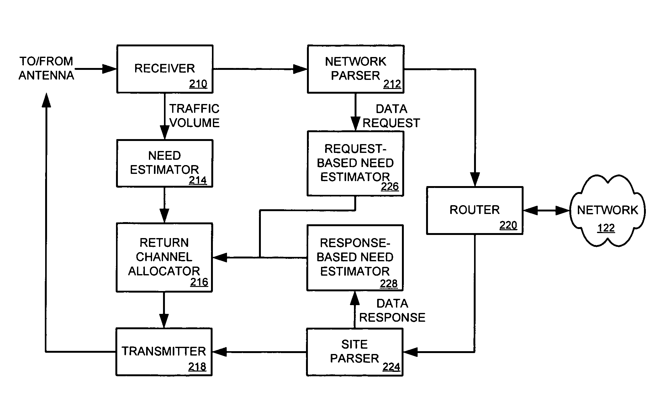
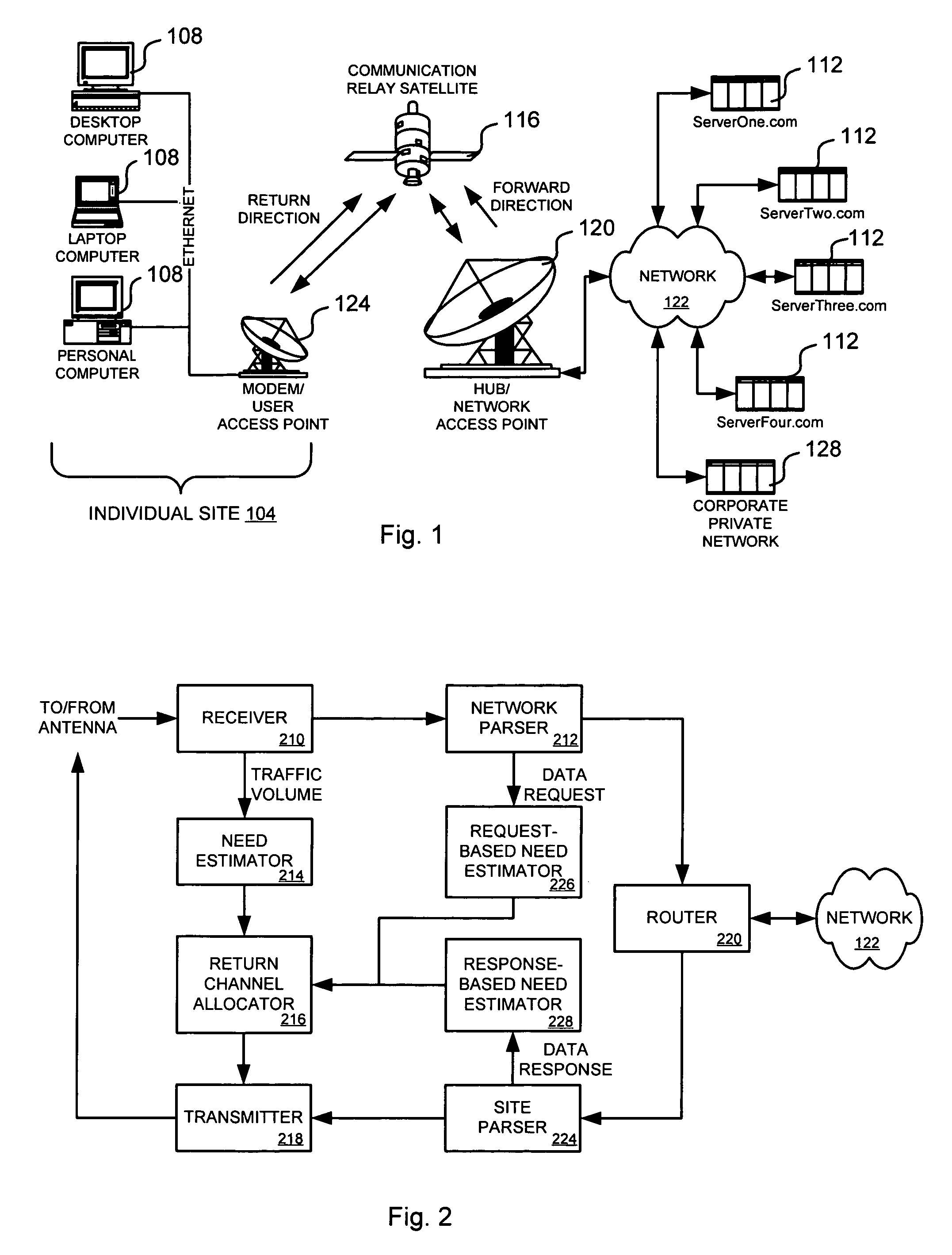
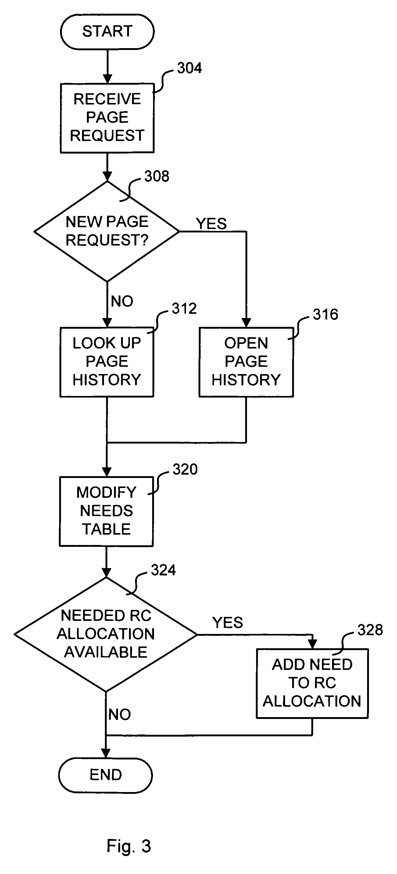
A communication system for providing network access over a shared communication link is disclosed. The communication system includes a user access point, a network access point and a communications link. The user access point is coupled to one or more user terminals that access a remote network. The network access point is coupled to the remote network. The communications link couples the user access point and the network access point. The communications link is at least partially controlled by the network access point, which monitors information passed between the remote network and the user access point to create an estimate of future usage of the communications link by the user access point based on the information. The network access point allocates communications link resources for the user access point based on the estimate.

Description

[0001]This application claims the benefit of and is a non-provisional of U.S. Patent Application Ser. No. 60 / 629,817 filed on Nov. 19, 2004, which is assigned to the assigner hereof and hereby expressly incorporated by reference in its entirety for all purposes.BACKGROUND OF THE DISCLOSURE[0002]This disclosure relates in general to networking and, more specifically, but not by way of limitation, to networking over controlled long delay links.[0003]Network access via satellite link has many speed limitations imposed by the long time delay of the link. Since the bulk of the Internet is composed of landline and short wireless links, communication delay has traditionally been associated with either slow or congested links. This bias has translated into standard protocols that create typical delays for satellite users that are much longer than just the sum of the typical landline delay plus the inherent satellite transmission delay.[0004]Since one of the main uses for the Internet is web...

Claims


Application Information

Patent Timeline
Patent Type & Authority Patents(United States)
IPC IPC(8): G06F15/173
CPCH04L41/0896H04L47/822H04L65/1036H04L67/322H04W72/10H04L67/02H04L67/28H04L69/24H04L47/70H04B7/18513H04L67/2819H04L47/781H04L47/824H04L2012/5608H04B7/185H04L67/56H04L67/564H04L67/61H04L47/83H04W74/004H04L43/0852H04L67/535H04W72/56H04L47/826H04W72/044
Inventor EIDENSCHINK, THOMAS
Owner VIASAT INC
Learn More