
Vacuum cleaner with multiple cyclonic dirt separators and bottom discharge dirt cup

a vacuum cleaner and cyclonic technology, applied in the field of vacuum cleaners, can solve the problems of reducing efficiency, negatively affecting airflow and reducing cleaning performan

Active Publication Date: 2010-08-10
BISSELL INC
View PDF37 Cites 124 Cited by
  • Summary
  • Abstract
  • Description
  • Claims
  • Application Information

AI Technical Summary

Benefits of technology

[0017]In a preferred embodiment, airflow inhibitors are present in the dirt-collecting bin to reduce the vertical component of the airflow, thereby tending to agglomerate and separate the dirt particles from the airflow.

Problems solved by technology

This creates a long air path with multiple parts which may allow for air leaks and generally negatively impacting airflow and, necessarily, cleaning performance.
The motor / fan assembly is in a vertical position below the cyclone which is undesirable due to the amount of space needed at the bottom of the handle.
This path introduces a number of turns which tends to create backpressure and therefore reduce efficiency.

Method used


Image

  • Vacuum cleaner with multiple cyclonic dirt separators and bottom discharge dirt cup
  • Vacuum cleaner with multiple cyclonic dirt separators and bottom discharge dirt cup
  • Vacuum cleaner with multiple cyclonic dirt separators and bottom discharge dirt cup

Examples


Embodiment Construction

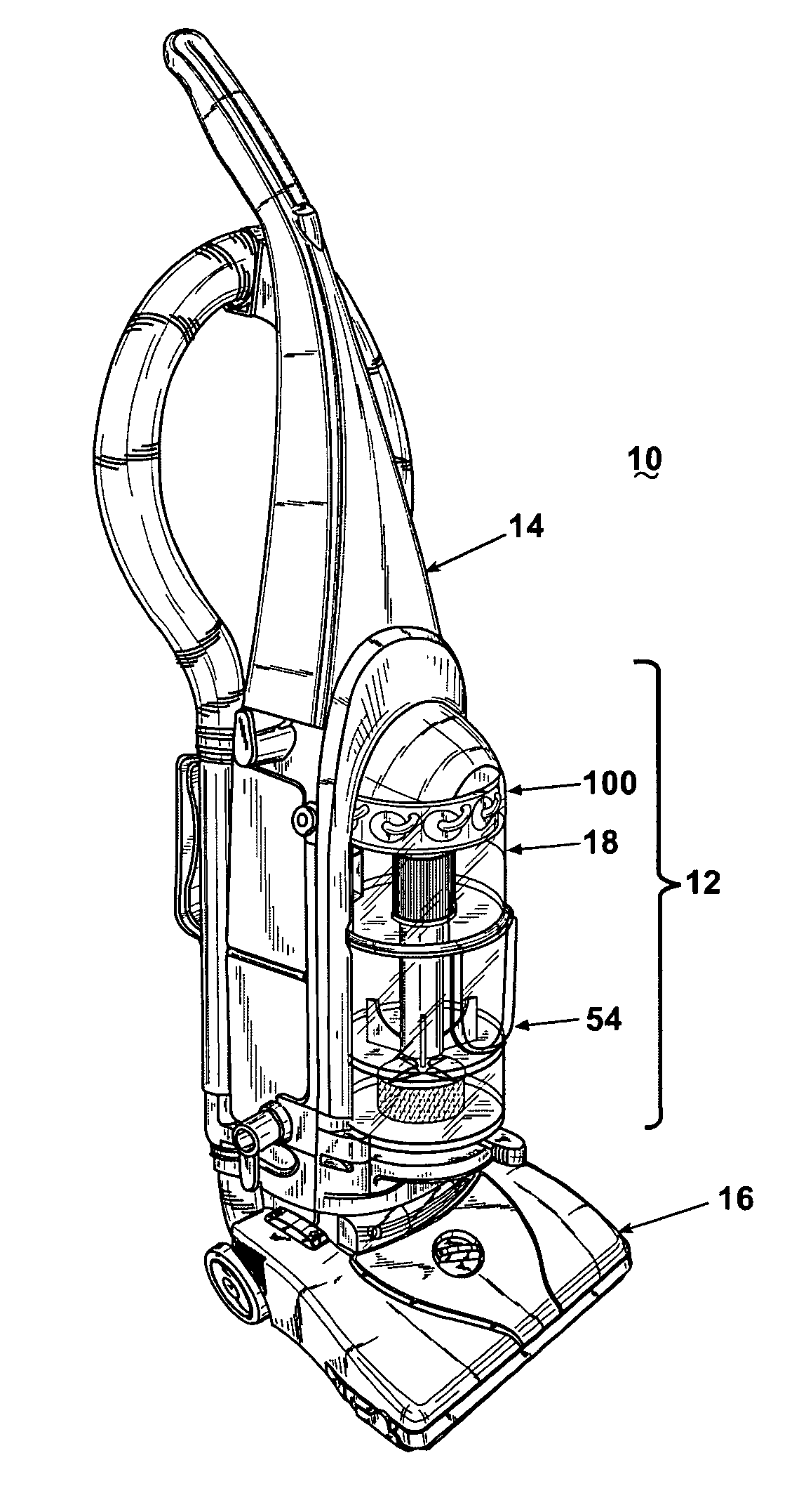
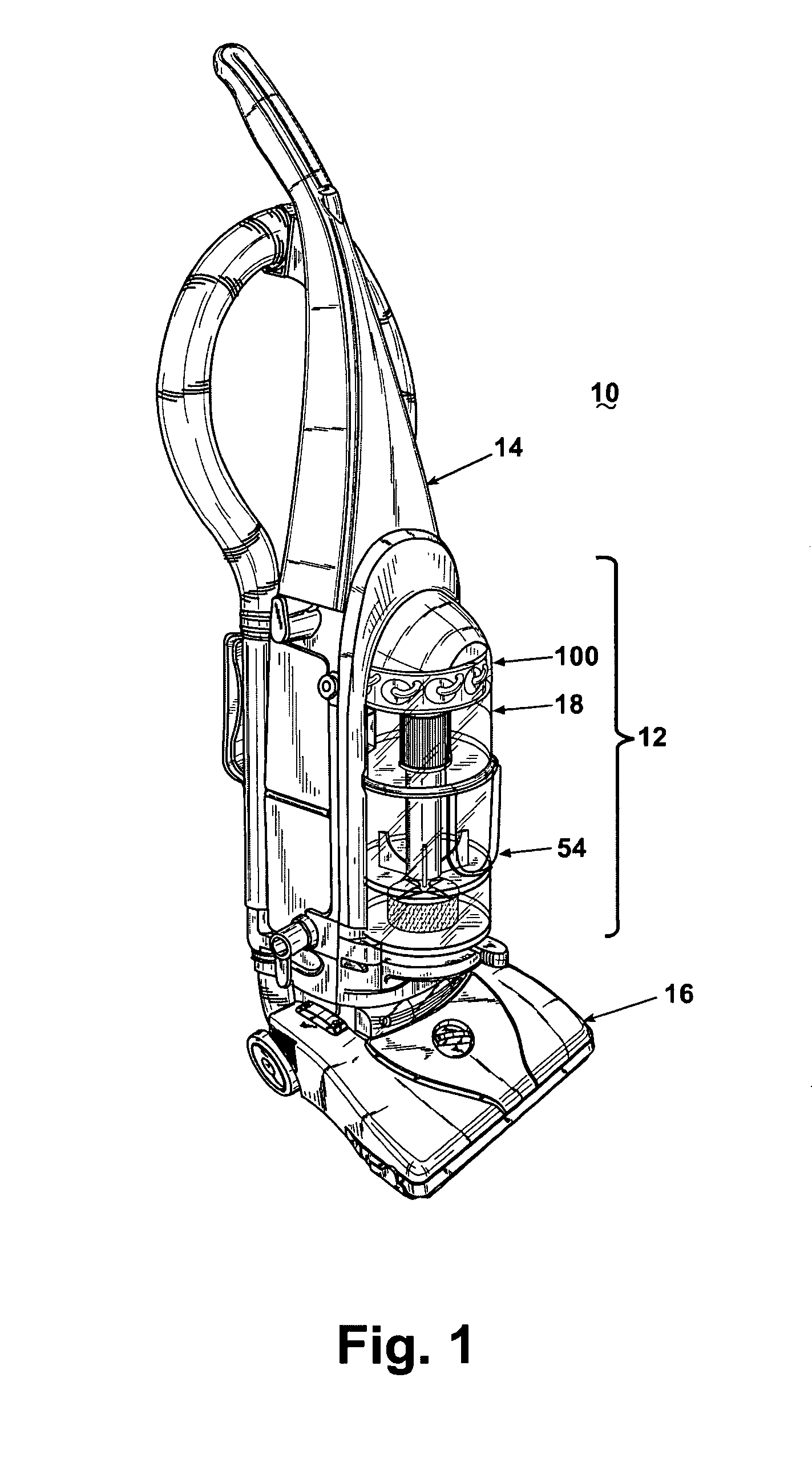
[0029]An upright vacuum cleaner 10 with cyclonic dirt separator and dirt cup assembly 12 according to the invention is shown in FIG. 1, comprising an upright handle 14 pivotally mounted to a nozzle base 16. The upright handle 14 mounts the cyclonic dirt separator and dirt cup assembly 12 according to the invention.

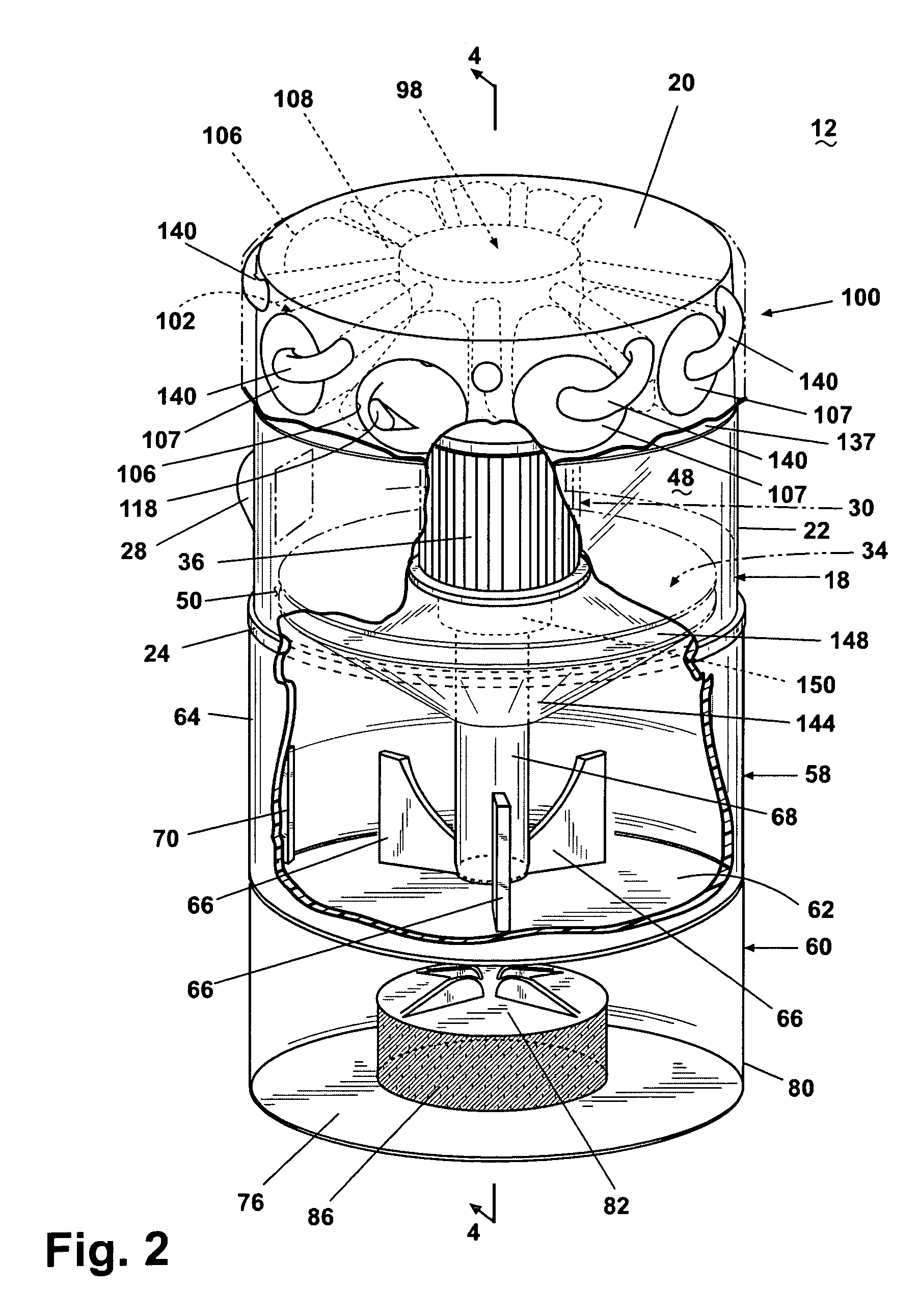
[0030]Referring to FIG. 2-4, the cyclonic dirt separator and dirt cup assembly 12 comprises a cylindrical cyclone separator 18 with an upper wall 20 and a sidewall 22, the sidewall 22 terminating in a lower offset lip 24. The sidewall 22 further includes a tangential air inlet 28 aligned proximate the upper wall 20 for generating a tangential airflow in the separator 18 parallel to the upper wall 20.

[0031]The cyclonic dirt separator 18 further comprises an exhaust assembly 30. The exhaust assembly 30 comprises a hollow cylindrical louver cage 32 mounted on a separator plate 34. The louver cage 32 further comprises a plurality of louvers 36 cylindrically arranged between a ...


PUM


Abstract

A vacuum cleaner with a first cyclonic dirt separation and a secondary cyclonic dirt separation and a bottom dirt-collecting bin beneath the first cyclone separator and a filter beneath the dirt cup and between the dirt cup and a suction source inlet. The secondary cyclones oriented generally perpendicular to the first cyclone separator. A separator plate separates the cyclone separator from the dirt cup. Fins project from a sidewall of the dirt tank, and fingers projecting from a bottom wall of the dirt tank. A hollow standpipe in the dirt cup transports working air from the cyclone separator outlet to the filter.

Description

CROSS REFERENCE TO RELATED APPLICATIONS[0001]This application claims the benefit of U.S. Provisional Patent Application Ser. No. 60 / 521,466, filed Apr. 30, 2004, which application is incorporated herein by reference in its entirety.FIELD OF THE INVENTION[0002]The invention relates to suction cleaners, and in particular to suction cleaners having cyclonic dirt separation. In one of its aspects, the invention relates to a separator with a cyclonic airflow path to separate dirt and debris from air drawn into the cleaner. In another of its aspects, the invention relates to a separator that deposits the dirt and debris in a collection receptacle. In another of its aspects, the invention relates to a bottom discharge dirt cup with an integrated filter chamber. In another of its aspects, the invention relates to multiple cyclone separators including a single primary cyclone in series with a plurality of secondary cyclones arranged in parallel.DESCRIPTION OF THE RELATED ART[0003]Cyclone sep...

Claims


Application Information

Patent Timeline
IPC IPC(8): A47L9/10
CPCA47L9/1641A47L9/1683
Inventor FESTER, JOSEPH A.
Owner BISSELL INC
Learn More