Interactive amusement park attraction vehicle

a technology for amusement parks and attraction vehicles, applied in the direction of amusements, roundabouts, switchbacks, etc., can solve problems such as the rolling of the apparatus, and achieve the effect of preventing damage or scratching

Inactive Publication Date: 2010-08-10
UNIV OF SOUTH FLORIDA
View PDF10 Cites 9 Cited by
  • Summary
  • Abstract
  • Description
  • Claims
  • Application Information

AI Technical Summary

Benefits of technology

[0010]In another embodiment the sphere is constructed from two matching hemispheres. The sphere can be opaque, having a view screen inside to project images to the rider(s), substantially transparent, louvered, or perforated to allow vision there through. In a more specific embodiment the sphere is louvered or perforated such that its rotation creates the illusion, to the rider(s), that the sphere is invisible. The sphere can be equipped with shock absorbent pads placed on its surface to prevent direct contact with the ground or track to prevent damage, or scratching.
[0011]In another embodiment, a plurality of rollers disposed on the side of the inner carriage opposite the seat maintain contact with the inner surface of the sphere, this helps the carriage maintain the proper attitude as the sphere rolls. The rollers are any device, or configuration, that allows the inner carriage to substantially maintain the proper attitude and illustrative devices include wheels, ball bearings and casters. A control mechanism can vary, i.e. brake, the rotation of the rollers; thereby creating friction on the inner surface of the hollow sphere and changing the path of the sphere.
[0013]In another embodiment, the invention includes a weight mounted within the sphere with a control adapted for altering the position of the weight, most commonly laterally. The lateral movement of the weight alters the combined center of gravity of the sphere, carriage and rider(s); thereby altering the sphere's path of travel.

Problems solved by technology

Rotation of the drive wheel against the inner surface of the sphere causes the apparatus to roll.

Method used


Image

  • Interactive amusement park attraction vehicle
  • Interactive amusement park attraction vehicle
  • Interactive amusement park attraction vehicle

Examples


Embodiment Construction

[0028]In the following detailed description of the preferred embodiments, reference is made to the accompanying drawings, which form a part hereof, and within which are shown by way of illustration specific embodiments by which the invention may be practiced. It is to be understood that other embodiments may be utilized and changes may be made without departing from the scope of the invention.

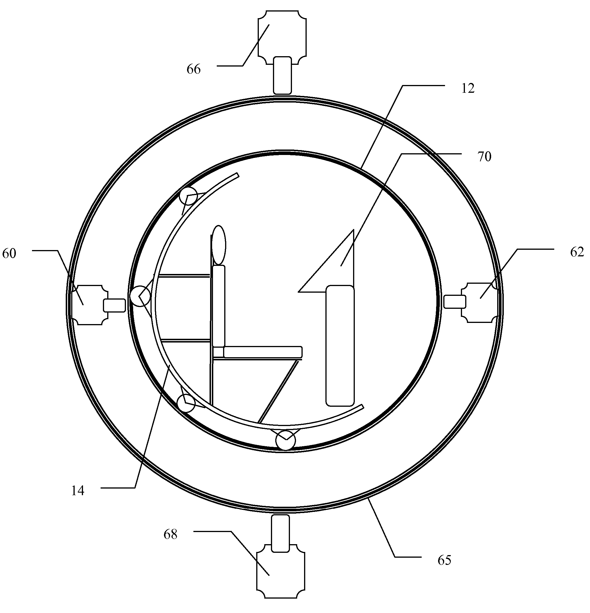
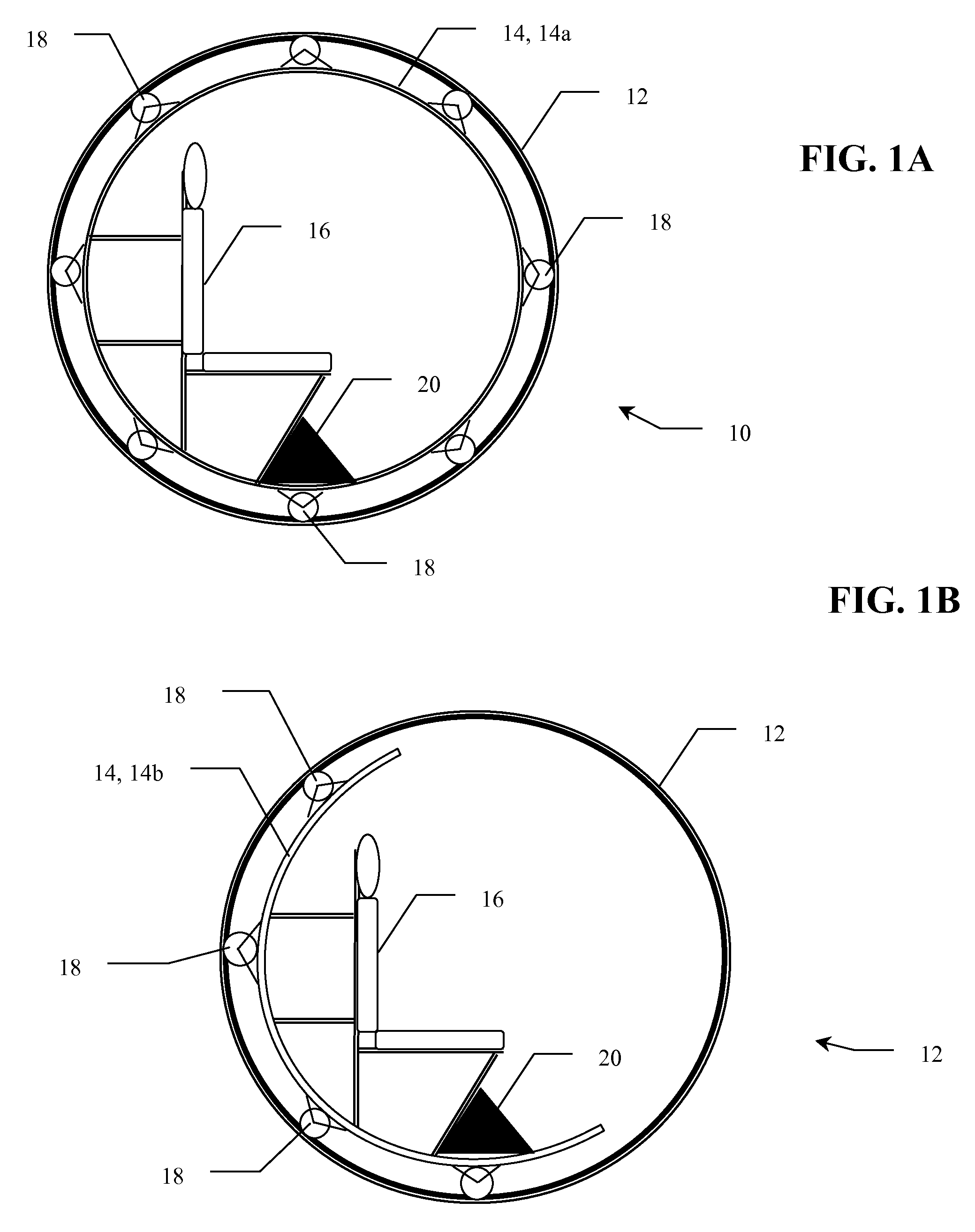
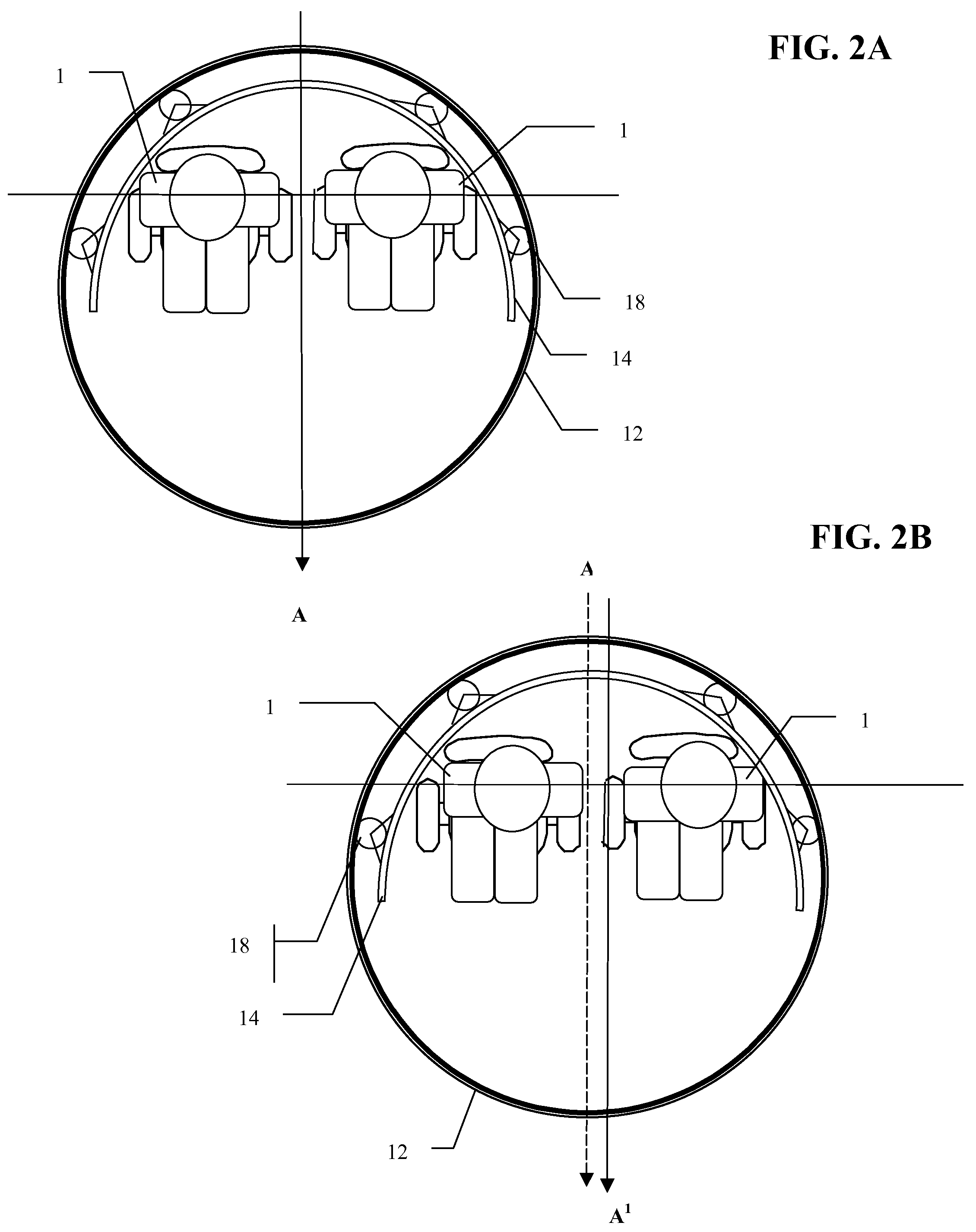
[0029]FIGS. 1A and 1B show alternate embodiments of vehicle 10 of the invention. FIG. 1A shows an embodiment wherein vehicle 10 comprises substantially hollow outer-sphere 12. Sphere 12 is hollow to accommodate inner carriage 14, formed as a sphere 14a, and seat 16. Carriage 14 is spaced apart from the inner surface of sphere 12 by rollers 18. Rollers 18 are in contact with the inner surface of sphere 12 but are fixedly mounted to carriage 14. In this manner, carriage 14 maintains a substantially constant attitude as sphere 12 rolls. Sphere 12 can be constructed from a variety of materials, inc...


PUM


Abstract

An apparatus capable of transporting a rider, specifically for an amusement ride. The apparatus is constructed in the form of a substantially hollow sphere which rides along the ground, which is preferably inclined, a track, or a predetermined path (being substantially flat but with guide rails or walls along its sides). An inner carriage, to which the rider's seat is attached, moves independently of the sphere and maintains a substantially constant attitude while the sphere rolls. The inner carriage can be formed in varying shapes such as a sphere, hemisphere, semicircle, tube or a circle.

Description

CROSS REFERENCE TO RELATED APPLICATIONS[0001]This application claims priority to currently U.S. Provisional Patent Application No. 60 / 725,030, filed Oct. 7, 2005.BACKGROUND OF THE INVENTION[0002]The roller coaster is a popular amusement ride developed for amusement parks and modern theme parks. Most roller coasters are made up of a track that rises and falls in intricate patterns; sometimes with one or more inversions (the most common being loops) that turn the rider briefly upside down. The track does not necessarily have to be a complete circuit (i.e. a “shuttle”). Most coasters have cars for two, four, or six passengers each, in which the passengers sit to travel around the track. Multiple cars are usually hooked together to form a train.[0003]The train design offers riders sitting in the front car a very different experience from those sitting in the rear car. While the riders in the rear car do not get an unobstructed view, the riders in the front car must wait for the rear car...

Claims


Application Information

Patent Timeline
Patent Type & Authority Patents(United States)
IPC IPC(8): A63G1/00
CPCA63G7/00A63G29/00
Inventor KOVAC, MICHAEL G.
Owner UNIV OF SOUTH FLORIDA
Why Eureka
Try Eureka