Rotatable stapling head of a surgical stapler

a stapling head and stapler technology, applied in the direction of surgical staples, paper/cardboard containers, manufacturing tools, etc., can solve the problems of inability to solve the problem of incomplete cutting of excess tissue around the wound, requiring too much strength, and affecting patient health, so as to achieve less strength

Active Publication Date: 2010-08-10
TOUCHSTONE INTERNATIONAL MEDICAL SCIENCE CO LTD
View PDF19 Cites 1435 Cited by
  • Summary
  • Abstract
  • Description
  • Claims
  • Application Information

AI Technical Summary

Benefits of technology

[0003]The invention is aimed at solving the problems of prior art by providing a rotatable stapling head of a surgical stapler which can cut the unwanted tissue around the wound completely but with less strength from the operator.
[0018]The present invention has following advantages: 1. It enables rotating cutting. 2. It enables active rotating. 3. It reduces anti-force from cutting tissue. 4. It reduces wounds caused by stretching in the process of cutting. 5. It is more safe and stable to cut tissue in surgery operations. 6. It requires less force from the surgical stapler operator.

Problems solved by technology

In the process of anastomosis stapling with a prior art stapling head of a surgical stapler, its annular scalpel moves in beeline which requires much strength from a surgical operator to complete cutting operation, and also it is easily apt to cut the excess tissue around the wound incompletely which is harmful to patient health.
But in practice, the improvements mentioned above are unable to solve the problems of cutting the excess tissue around the wound incompletely and requiring too much strength.

Method used


Image

  • Rotatable stapling head of a surgical stapler
  • Rotatable stapling head of a surgical stapler
  • Rotatable stapling head of a surgical stapler

Examples


embodiment 1

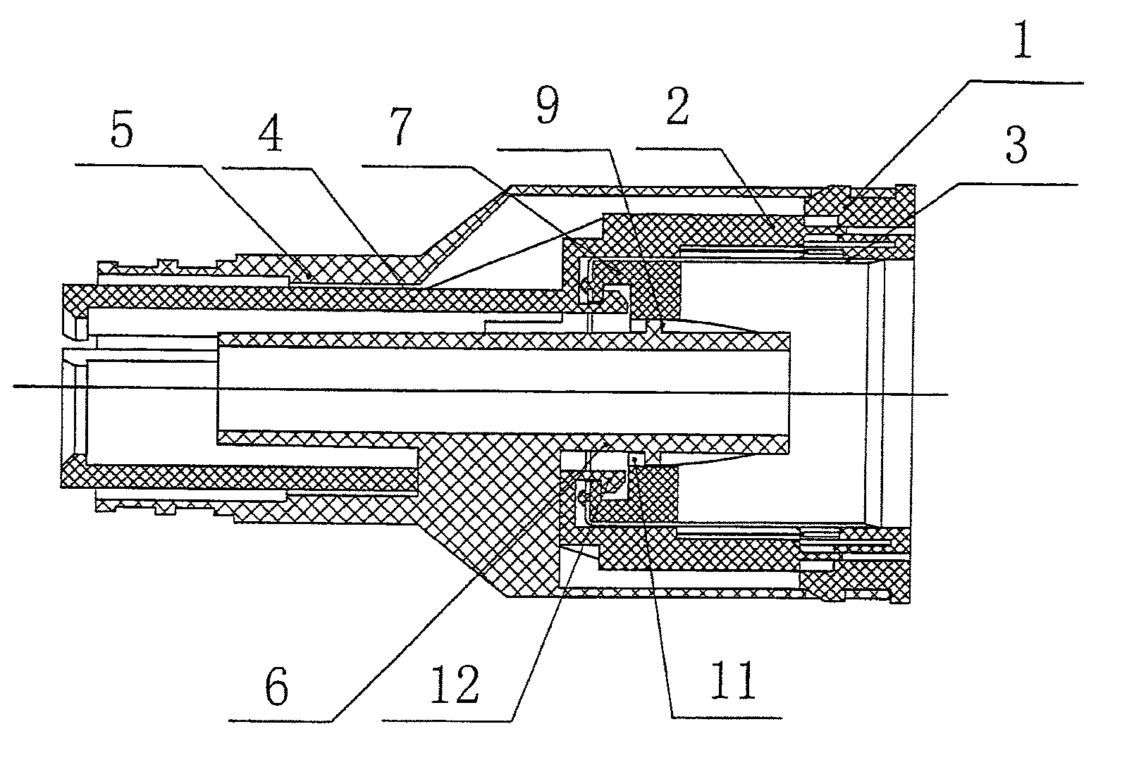
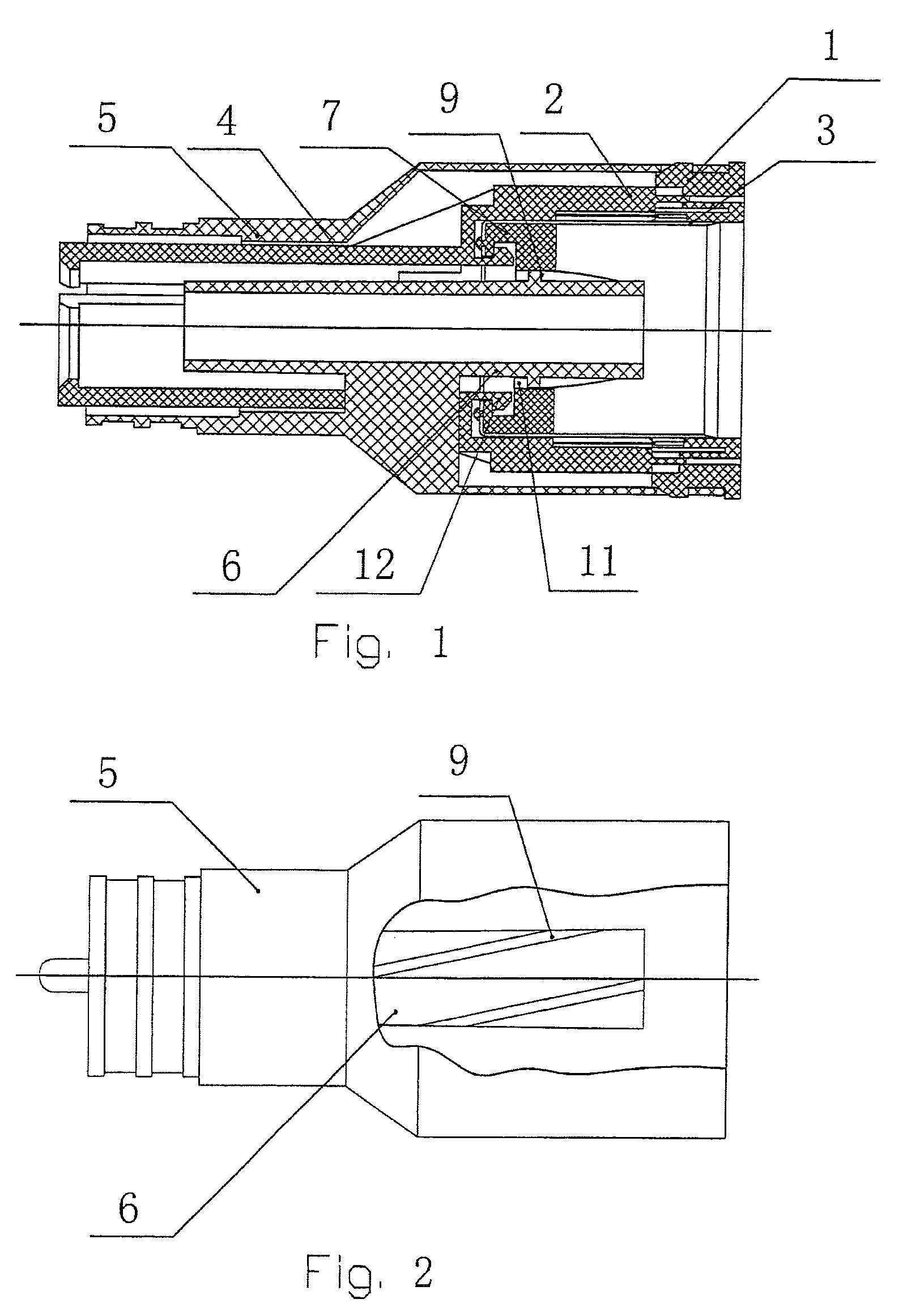
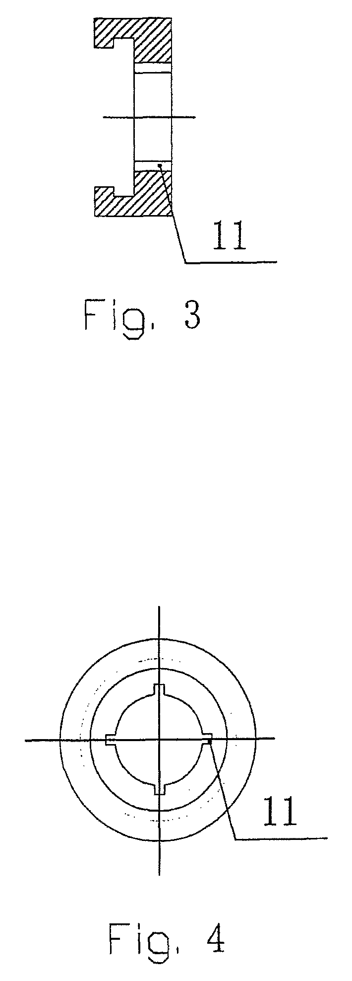
[0041]As shown in FIGS. 1 and 2, the staple driver 2 and the compression rod 4 are made integral, the rotating sleeve 7 is disposed at the inner bottom of the annular scalpel 3; the hook 12 is disposed at the bottom of the front cavity of the staple driver 2 so as to hook with the bottom of the annular scalpel 3. When the staple driver 2 is pushed forward, it drives the rotating sleeve 7 and the scalpel 3 to move forward, meanwhile, the concave-convex structure 11 of the rotating sleeve 7 matches with the spiral track 9 of the support tube 6 in the staple casing so as to drive the rotating sleeve 7 to rotate. Because the rotating sleeve 7 is riveted with the scalpel 3, the scalpel 3 rotates along with the rotating sleeve 7. After stapling, the scalpel 3 and the rotating sleeve 7 retract back to the staple casing by the force from the hook 12 which is disposed on the staple driver.

embodiment 2

[0042]As shown in FIG. 5, the staple driver 2 and the compression rod 4 are made integral, the rotating sleeve 7 is disposed at the outer bottom of the annular scalpel 3; the hook 12 is disposed at the bottom of the front cavity of the staple driver 2 so as to hook with the bottom of the rotating sleeve 7. When the staple driver 2 is pushed forward, it drives the rotating sleeve 7 and the scalpel 3 to move forward, meanwhile, the concave-convex structure 11 of the rotating sleeve matches with the spiral track 9 of the support tube 6 in the staple casing so as to drive the rotating sleeve 7 to rotate. Because the rotating sleeve 7 is riveted with the scalpel 3, the scalpel 3 rotates along with the rotating sleeve 7. After stapling, the scalpel 3 and the rotating sleeve 7 retract back to the staple casing by the force from the hook 12 which is disposed on the staple driver.

embodiment 3

[0043]As shown in FIG. 6, the staple driver 2 and the compression rod 4 are made integral, the rotating sleeve 7 is disposed at the inner bottom of the annular scalpel; a fixed spiral sleeve 13 is fixed outside the support tube 6, the spiral track 9 is disposed on the outer wall of the fixed spiral sleeve, the support tube 6 has a threaded insert 8 on its front end with a limit fastening nut 10 disposed thereon. A hook 12 is disposed at the bottom of the front cavity of the staple driver 2 so as to hook with the bottom of the rotating sleeve 7. When the staple driver 2 is pushed forward, it drives the rotating sleeve 7 and the scalpel 3 to move forward, meanwhile, the concave-convex structure 11 of the rotating sleeve matches with the spiral track 9 of the fixed spiral sleeve so as to drive the rotating sleeve 7 to rotate. Because the rotating sleeve 7 is riveted with the scalpel 3, the scalpel rotates along with the rotating sleeve 7. After stapling, the scalpel 3 and the rotating ...


PUM

PropertyMeasurementUnit
shapeaaaaaaaaaa
concave-convex structureaaaaaaaaaa
strengthaaaaaaaaaa

Abstract

The present invention provides a rotatable stapling head of a surgical stapler, which comprises a staple cartridge (1), a staple driver (2), a scalpel (3), a compression rod (4), a staple casing (5) and a rotating assembly. The above parts constitute a rotating forward mechanism which can rotatablely forward the scalpel therein.

Description

FIELD OF THE INVENTION[0001]The present invention generally relates to a stapling head of a surgical stapler, more particularly, to a rotatable stapling head of a surgical stapler.BACKGROUND OF THE INVENTION[0002]To perform anastomosis stapling operations, the following methods are used, such as manual sutures by needles, medical adhesive, surgical zip and surgical stapler, etc,. Among which a surgical stapler as a tool for tissue anastomosis is more and more widely used in surgery operations. In the process of anastomosis stapling with a prior art stapling head of a surgical stapler, its annular scalpel moves in beeline which requires much strength from a surgical operator to complete cutting operation, and also it is easily apt to cut the excess tissue around the wound incompletely which is harmful to patient health. Therefore, many improvements on stapling anvil have been made from overseas, such as annular severable anvil, anvil with steps thereon. Alternatively, some improvemen...

Claims


Application Information

Patent Timeline
Patent Type & Authority Patents(United States)
IPC IPC(8): A61B17/03
CPCA61B17/115A61B17/1114A61B17/1155A61B17/32053
Inventor CHEN, WANG-DONGCHEN, QUANLIN, JIANGLU, MING-YAOYIN, WEI-ZHONG
Owner TOUCHSTONE INTERNATIONAL MEDICAL SCIENCE CO LTD
Why Eureka
Try Eureka