Thermostatic mixing valve

a technology of thermostatic mixing and mixing valve, which is applied in the field of taps, can solve the problems of asymmetric thermal expansion, inconvenient operation, and inconvenient adjustment of flow rate, and achieve the effect of reducing friction and facilitating flow rate adjustmen

Active Publication Date: 2010-08-10
RUGA MANOLO +1
View PDF8 Cites 13 Cited by
  • Summary
  • Abstract
  • Description
  • Claims
  • Application Information

AI Technical Summary

Benefits of technology

[0023]Still another advantage of the present invention is a greater ease of adjustment of the flow rate, since the relevant control acts directly on the mobile disk without having to drag other members and therefore with a lower friction.
[0024]These and other advantages and characteristics of the valve according to the present invention will be clear to those skilled in the art from the following detailed description of an embodiment thereof, with reference to the annexed drawings wherein:
[0025]FIG. 1 is an exploded side view of the members which make up the above-mentioned valve, some of them being partially sectioned and others sectioned;
[0026]FIG. 2 is a schematic sectional side view showing the members of FIG. 1 in an assembled state; and
[0027]FIGS. 3 and 4 are perspective bottom views of the two ceramic disks making up the valve group and of the upper disk only, respectively.

Problems solved by technology

However, although known from some time, conventional thermostatic mixing valves still have some drawbacks of various nature.
A first drawback is the asymmetric thermal expansion that occurs when only hot water is delivered.
As a result they may not work properly, for example the slider may get stuck and thus affect the operation of the device.
A second kind of drawback comes from the calcareous encrustations, especially on the hot water side, which may jeopardize the correct operation of the device.
This problem stems from the fact that the slider travel is of a few tenths of a millimeter (usually max.
0.6 mm), therefore even small-size impurities may prove detrimental.
Still another kind of drawback is the use of a single control for temperature and flow rate, that implies a difficult repeatability of temperature between two openings.
Moreover, there is a poor precision in adjusting the temperature due to the limited travel of the single control, which generally has a maximum rotatory travel of 90° around the tap mouth (±45°).
However, even this solution is not free from drawbacks in that the flow rate control is a horizontal rotating lever located above the ring for the temperature adjustment.
Moreover, the above-described arrangement makes it difficult to reach the ring for the temperature adjustment, since the user has to insert his hand between the tap mouth and the lever above.
In any case, the more or less close coupling between the flow rate control and the temperature control leads to a mutual interference which may affect the device operation.

Method used


Image

  • Thermostatic mixing valve
  • Thermostatic mixing valve
  • Thermostatic mixing valve

Examples


Embodiment Construction

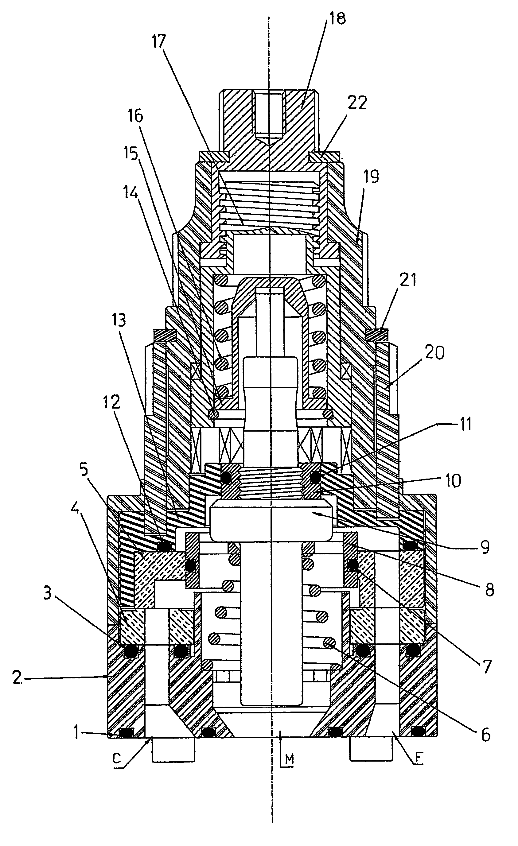
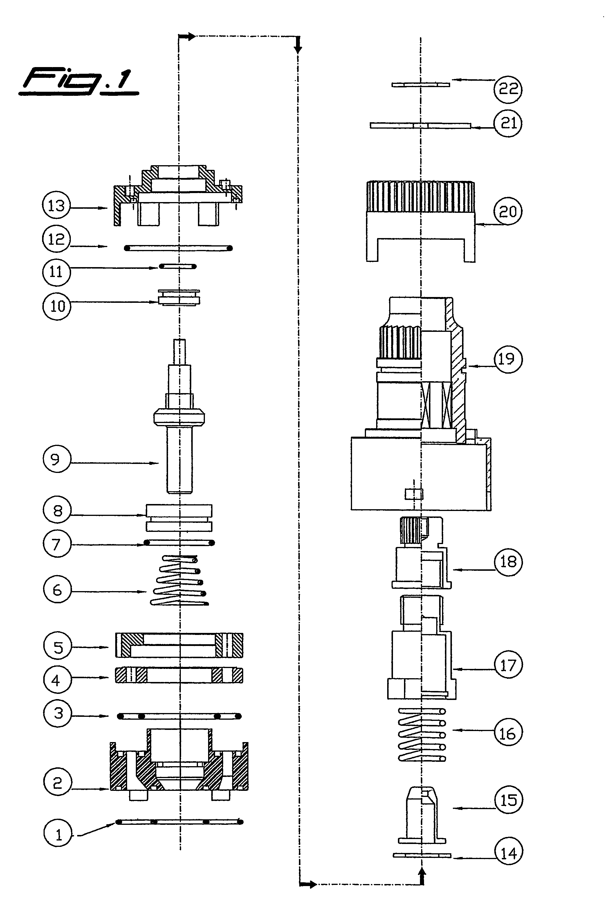
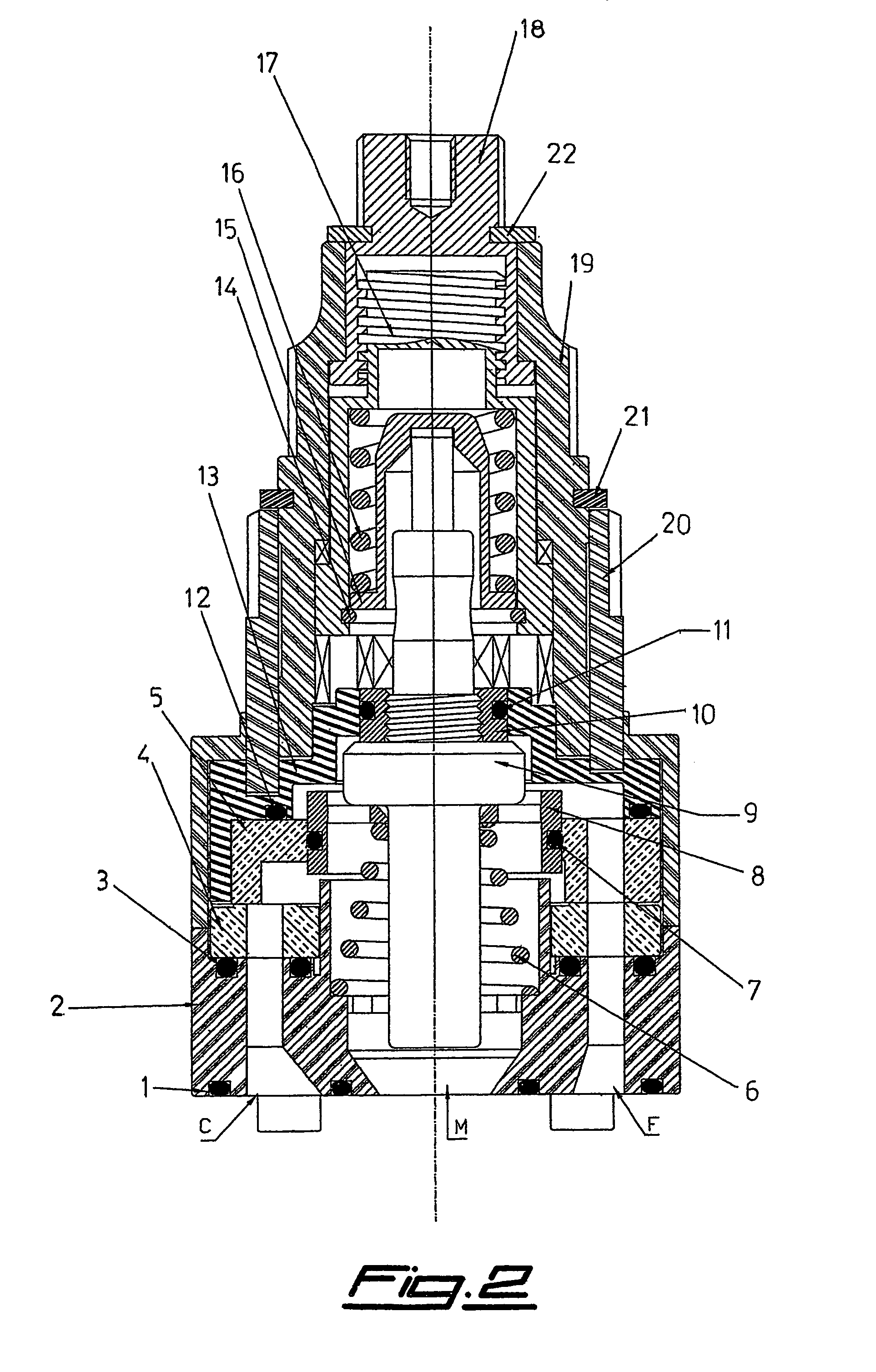
[0028]With reference to FIGS. 1 and 2, there is seen that a valve according to the present invention includes a valve group, described in greater detail further on, consisting of a mobile upper disk 5, a fixed lower disk 4, a lower gasket 3 and a base 2, below which a relevant gasket 1 is arranged for the mounting into the tap body. In base 2 there are formed lateral openings C, F for the inflow of hot and cold water, respectively, and the central opening M for the outflow of the mixed water.

[0029]Inside the valve group there are arranged a lower spring 6 pushing from below a slider 8 that sealingly slides, thanks to an O-ring 7, in disk 5 and is pushed from above by a thermostatic member 9 passing through it. On the latter there is screwed an insert 10 that, thanks to an O-ring 11, is sealingly introduced in the central opening of a member 13 that transmits the flow rate control.

[0030]Also the top face of the upper disk 5 is sealed, thanks to an O-ring 12, against said member 13, s...


PUM


Abstract

The invention relates to a thermostatic mixing valve in which the access path of the hot water to the mixing chamber is completely formed within a bottom base (2) and the ceramic disks (4, 5) of the valve group, the slider (8) of the thermostatic member sealingly sliding in a central seat of the upper disk (5). By having the hot water not pass through the metallic members of the valve it is possible to eliminate the problems of asymmetric thermal expansion of said metallic members when only hot water is delivered, and also to greatly reduce the problems of calcareous encrustations since the latter build up with difficulty on the ceramic material. Furthermore, the valve is manufactured with a compact and simplified structure, including a small number of pieces, with totally independent temperature and flow rate controls.

Description

CROSS-REFERENCE TO RELATED APPLICATIONS[0001]Not ApplicableSTATEMENT REGARDING FEDERALLY SPONSORED RESEARCH OR DEVELOPMENT[0002]Not ApplicableTHE NAMES OF THE PARTIES TO A JOINT RESEARCH AGREEMENT[0003]Not ApplicableBACKGROUND OF THE INVENTION[0004](1) Field of the Invention[0005]The present invention relates to taps for mixing hot and cold water in sanitary facilities (wash-basins, showers, bathtubs, etc.), and in particular to a cartridge mixing valve provided with a thermostatic device suitable to maintain a constant water temperature.[0006](2) Description of Related Art[0007]It is known that conventional single-control mixing taps include, a tap body with a cartridge mixing valve (hereinafter simply valve) removably inserted therein and a control lever for controlling a valve group, within the cartridge, made up of a pair of ceramic disks which adjust the flow of hot and cold water. This adjustment of the water, both in flow rate and in temperature, is carried out through the tr...

Claims


Application Information

Patent Timeline
Patent Type & Authority Patents(United States)
IPC IPC(8): G05D23/13
CPCG05D23/1353Y10T137/86823
Inventor RUGA, MANOLORUGA, OSVALDO
Owner RUGA MANOLO
Why Eureka
Try Eureka