Recording tape cartridge

a technology for recording tapes and cartridges, which is applied in the field of recording tape cartridges, can solve the problems of difficult to ensure the attachment region of the ic tag, the ic tag is difficult to attach to the back label side, and the ic tag is difficult to rotate the reel

Active Publication Date: 2010-08-10
FUJIFILM CORP
View PDF14 Cites 9 Cited by
  • Summary
  • Abstract
  • Description
  • Claims
  • Application Information

AI Technical Summary

Benefits of technology

[0008]Thus, the present invention provides a recording tape cartridge that can ensure an attachment region for an RFID (Radio Frequency Identification) inside a case.
[0018]According to the recording tape cartridge of this configuration, disposing the RFID between the regulating wall that defines the housing area of the reel and the holding wall that is formed the predetermined distance away from the outer peripheral surface of the regulating wall can be done easily by a robot hand or the like.

Problems solved by technology

However, in the case of a one-reel type recording tape cartridge, the size of the entire one-reel type recording tape cartridge is about half the size of a two-reel type video cassette, so the size of the back label side thereof is also about half, and it becomes difficult to attach the IC tag to the back label side.
Further, when the IC tag is adhered by an adhesive to the inside of the case, there arises the problem that rotation of the reel is hindered by the IC tag when the IC tag peels off inside the housing area of the reel as a result of degradation over time (a drop in the durability) of the adhesive.
In this manner, there is the problem that, when an IC tag that has a certain size (area) is to be attached to the inside of a case of a recording tape cartridge, it is difficult to ensure an attachment region for the IC tag.

Method used


Image

  • Recording tape cartridge
  • Recording tape cartridge
  • Recording tape cartridge

Examples


Embodiment Construction

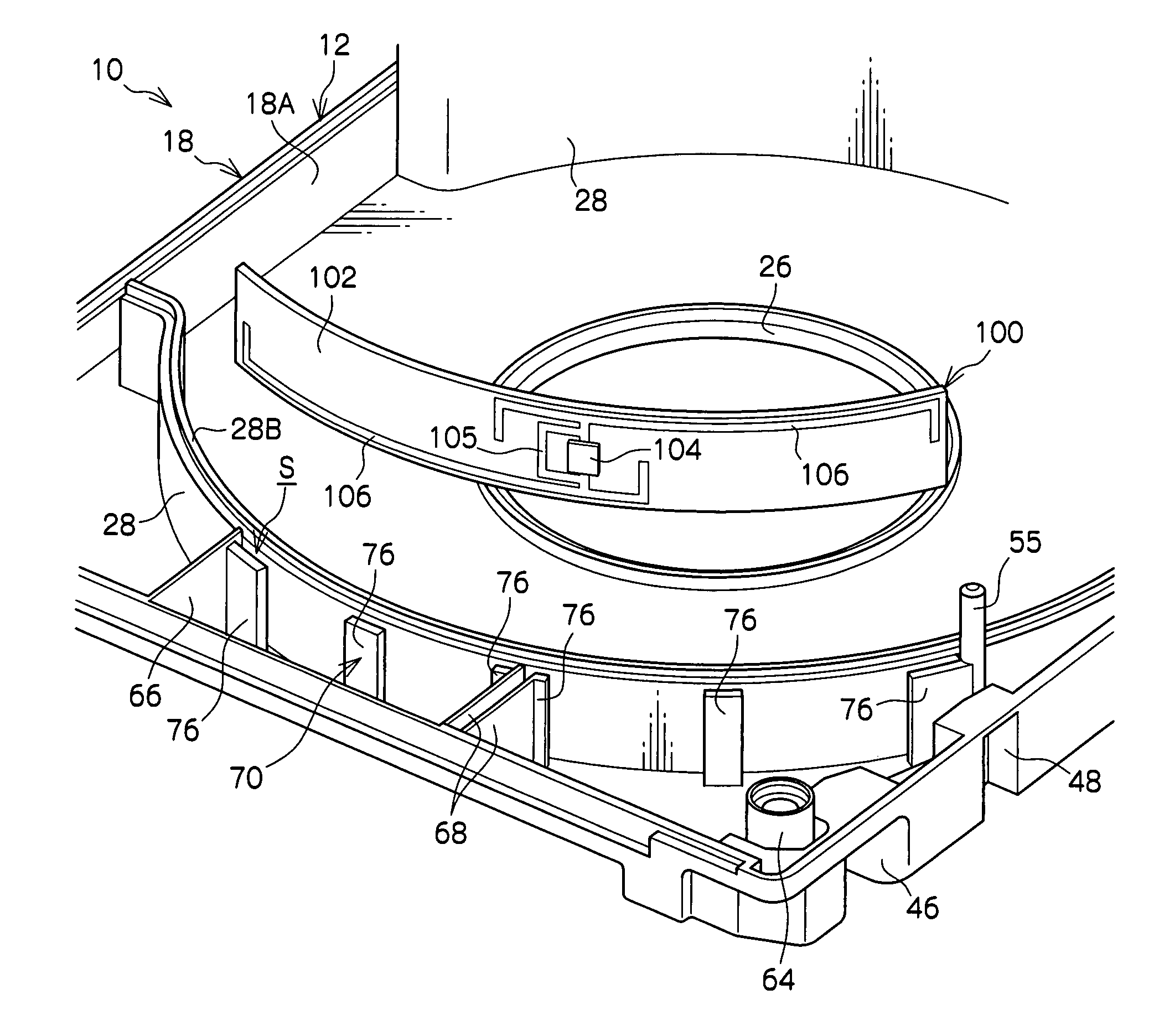
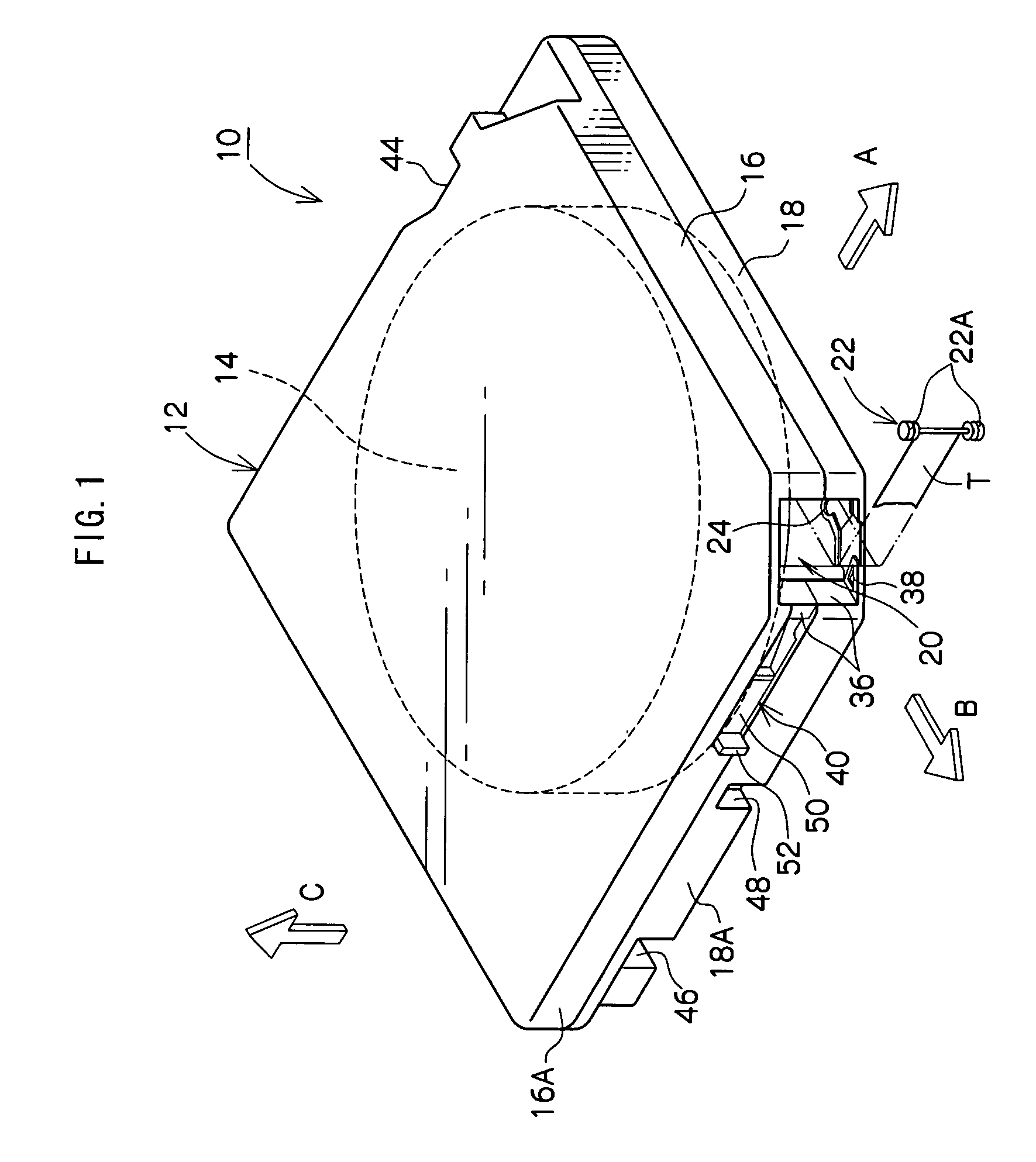
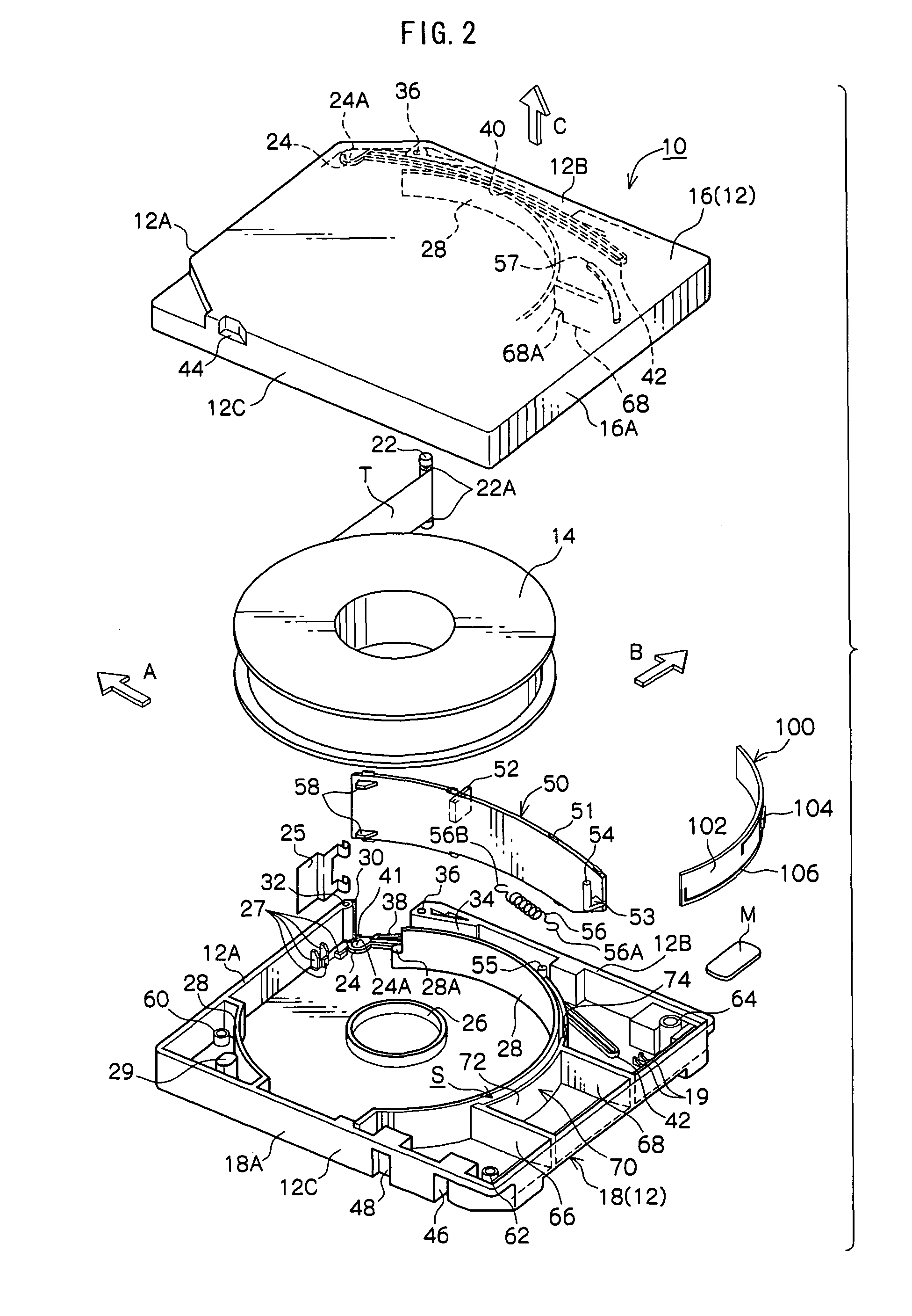
[0030]Below, the best modes for implementing the present invention will be described in detail on the basis of embodiments shown in the drawings. For the sake of convenience of description, in FIG. 1, arrow A represents the direction in which a recording tape cartridge 10 is loaded into a drive device (not shown) and will be referred to as a front direction (front side) of the recording tape cartridge 10. Additionally, the direction of arrow B, which is orthogonal to arrow A, will be referred to as a right direction (right side). Further, arrow C represents a direction that is orthogonal to the direction of arrow A and the direction of arrow B and will be referred to as an upper direction (upper side) of the recording tape cartridge 10.

[0031]As shown in FIG. 1 to FIG. 4, the recording tape cartridge 10 is configured such that a reel 14, around which is wound recording tape T such as magnetic tape that is an information recording and reproducing medium, is rotatably and singly housed...


PUM

PropertyMeasurementUnit
heightaaaaaaaaaa
heightaaaaaaaaaa
heightaaaaaaaaaa

Abstract

A recording tape cartridge comprises: a case that comprises an upper case and a lower case and houses a reel around which recording tape is wound; a regulating wall that is formed at least on the lower case and defines an area in which the reel is housed; a holding wall that is formed a predetermined space away from an outer peripheral surface of the regulating wall; and an RFID that is housed in the space between the regulating wall and the holding wall.

Description

CROSS-REFERENCE TO RELATED APPLICATION[0001]This application claims priority under 35 USC 119 from Japanese Patent Application No. 2008-091000, filed Mar. 31, 2008, the disclosure of which is incorporated by reference herein.BACKGROUND OF THE INVENTION[0002]1. Field of the Invention[0003]The present invention relates to a recording tape cartridge where recording tape such as recording tape that is used as a recording and reproducing medium mainly for computers and the like is housed inside a case.[0004]2. Description of the Related Art[0005]Conventionally, there have been known recording tape cartridges where recording tape such as magnetic tape that is used as a data recording and reproducing medium (data backup) for computers and the like is wound around a reel that is made of a synthetic resin and where the reel is singly housed inside a case. Sometimes a non-contact memory board, in which various information such as the recording capacity and the recording format of the recordin...

Claims


Application Information

Patent Timeline
Patent Type & Authority Patents(United States)
IPC IPC(8): G11B23/107
CPCG11B23/042G11B23/045G11B23/08714G11B23/107
Inventor SUMIYA, YOSUKETAKENOSHITA, KENJIONMORI, SHOZO
Owner FUJIFILM CORP
Why Eureka
Try Eureka