Branched stent delivery system

a delivery system and stent technology, applied in the field of branched stent delivery system, can solve the problems of more incision sites in the patient's body, and complicated placement of such a bifurcated devi

Active Publication Date: 2010-08-10
WL GORE & ASSOC INC
View PDF19 Cites 19 Cited by
  • Summary
  • Abstract
  • Description
  • Claims
  • Application Information

AI Technical Summary

Benefits of technology

[0004]The present invention further provides an interventional delivery system comprising: a first catheter having at its distal end a side branch vessel segment; a second catheter attached around the first catheter and having at its distal end a main vessel segment; and a side branch vessel device attached to the side branch vessel segment of the first catheter wherein the main vessel segment and the side branch vessel device are simultaneously delivered to a treatment site, and further wherein the second catheter has an opening in a side wall near the distal end of the second catheter to allow for passage of the side branch vessel segment of the first catheter. The second catheter may comprise a capture tube which surrounds the bifurcated guidewire and facilitates for the ease of bifurcated guidewire removal from a vessel. A bifurcated guidewire with at least two distal tips may be used with the first catheter. The two distal tips face opposing directions, wherein one of the two distal tips is the leading end and one of the tips is a reverse facing tip end.
[0006]A method of deploying a branched stent assembly is also provided comprising: advancing a catheter assembly on a bifurcated guidewire to a treatment site; orienting the catheter assembly in the main vessel; pulling the bifurcated guidewire to orient the guidewire reverse facing tip into the side branch vessel; deploying the main vessel device in the main vessel; then advancing the side branch vessel device to a desired location; and deploying the side branch device. After stent deployment, removal of the delivery assembly is facilitated by advancing the guidewire and first catheter forward until the guidewire reverse facing tip and reverse facing portion of the first catheter are retracted from the side branch vessel allowing removal of the bifurcated guidewire along with the first and second catheters.

Problems solved by technology

Placement of such a bifurcated device can be rather complicated, and often involves approaching the bifurcated section of the artery through at least two side branches or through the trunk plus one side branch.
The procedure is not only time consuming, but can also lead to more incision sites in the patient's body and can necessitate more complicated maneuvers for the surgeon.

Method used


Image

  • Branched stent delivery system
  • Branched stent delivery system
  • Branched stent delivery system

Examples


Embodiment Construction

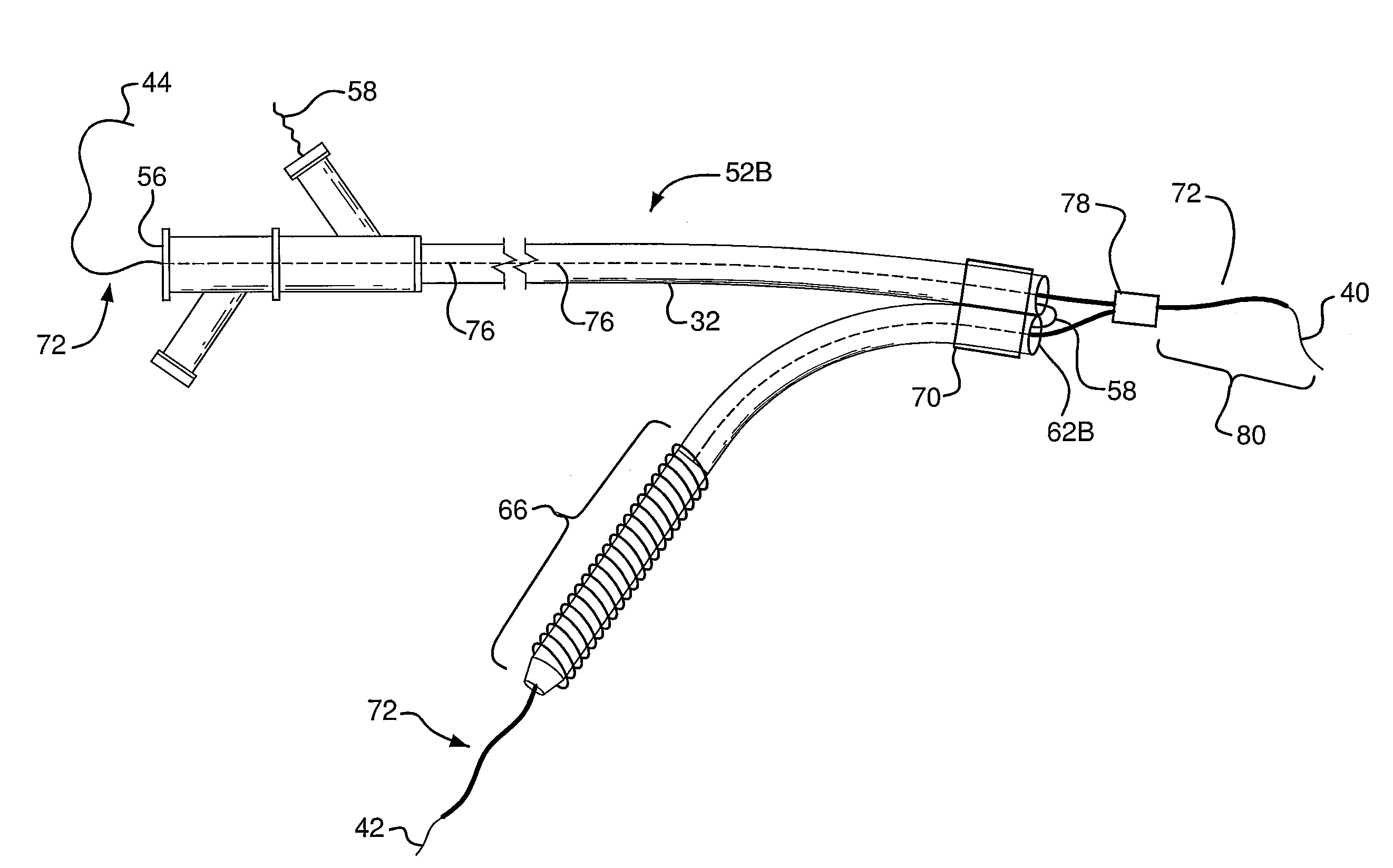
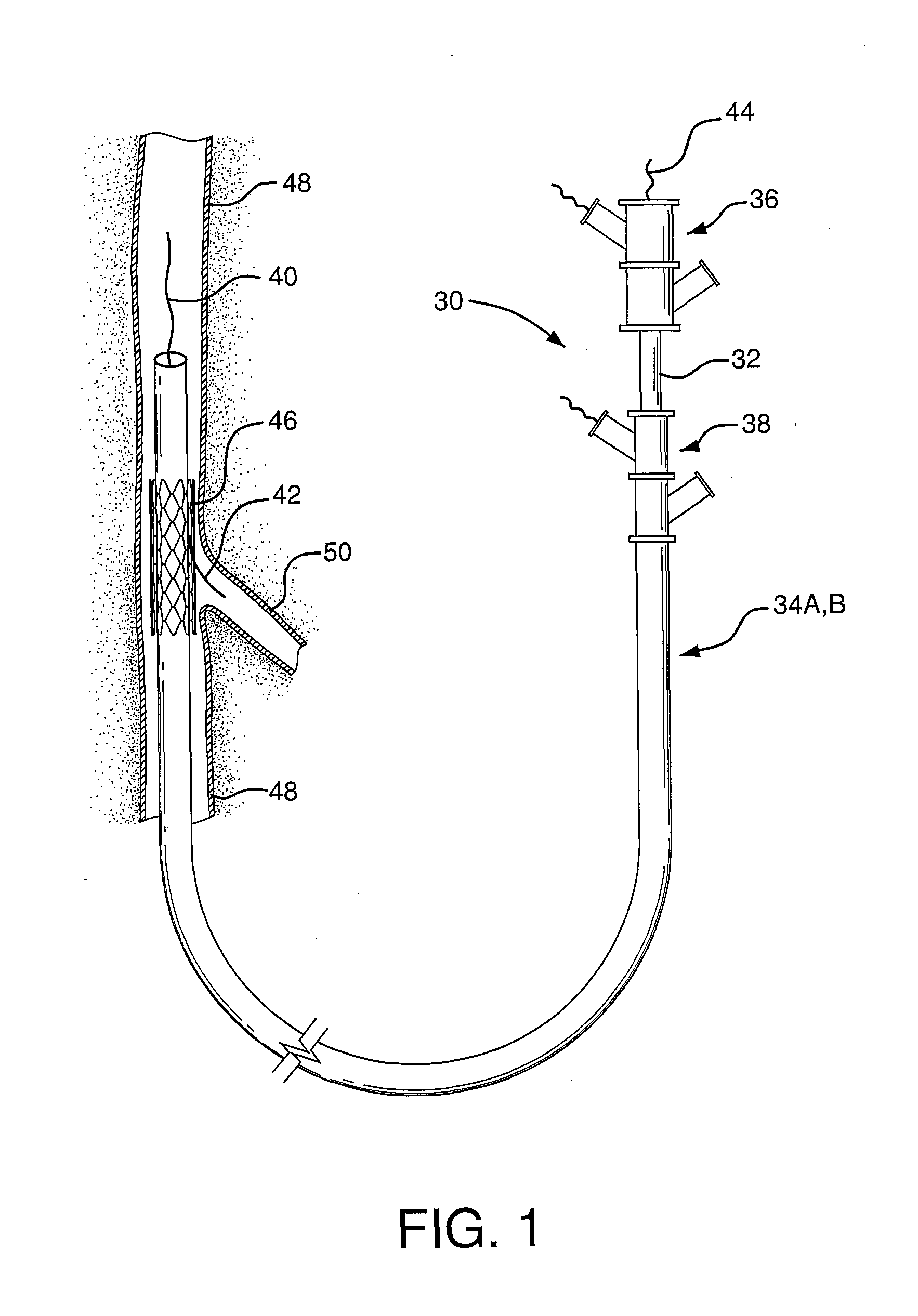
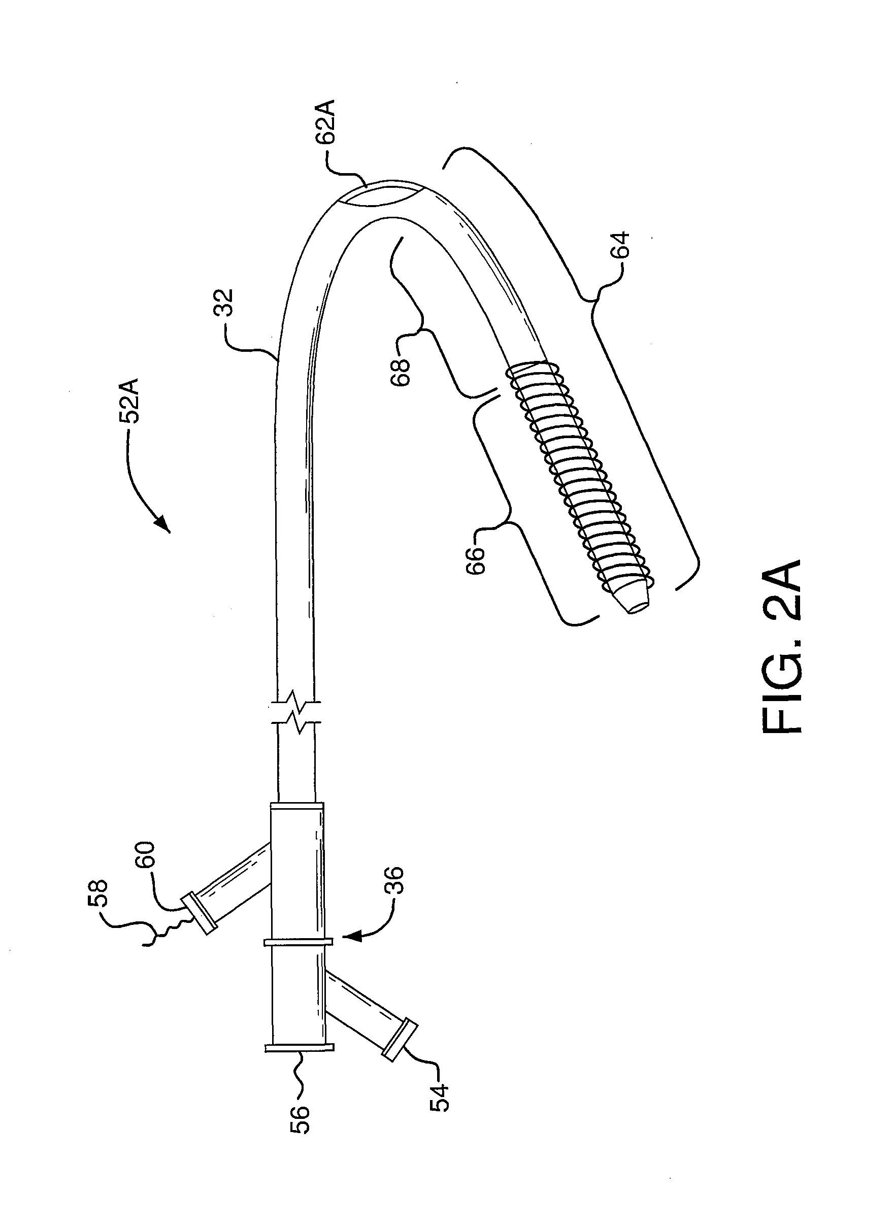
[0024]The present invention provides an interventional delivery system for the placement of bifurcated stent grafts into acutely angled vasculature. Acutely angled vasculature may exist in renal vessels, subclavian arteries, biliary ducts, prostate vessels, and other non-vascular applications as well. The challenge in stent placement is deployment from a main vessel such as a femoral artery to a reverse acute angle vessel. The present invention provides a device and procedure which decreases the number and size of incisions required to place bifurcated stent grafts into acutely angled vasculature, and further reduces the required surgical steps and patient trauma associated with this traditionally more complex medical procedure. As shown in FIG. 1, the present invention provides an interventional delivery system 30 comprising a first catheter shaft 32, a second catheter assembly 34A or 34B, a first catheter hub assembly 36, a second catheter hub assembly 38, a bifurcated guidewire l...


PUM


Abstract

An interventional delivery system with a first catheter having at its distal end a side branch vessel segment; a second catheter attached around the first catheter and having at its distal end a main vessel segment; a side branch vessel device attached to side branch vessel segment of the first catheter; and main vessel device attached to the main vessel segment of the second catheter. The main vessel device and the side branch vessel device are able to be simultaneously delivered to a treatment site.

Description

BACKGROUND OF THE INVENTION[0001]The present invention generally relates to a delivery system and method for delivering an expandable endoluminal prosthetic device such as a stent graft and more particularly to a device and method for placing an acutely angled bifurcated stent graft through a single access incision. Expandable surgical devices such as stents or stent grafts are used in a variety of places in the human body to repair aneurysms and to support various anatomical lumens, such as blood vessels, respiratory ducts, gastrointestinal ducts, and the like.[0002]Conventionally, these devices are deployed across an aneurysm or in the regions of a stenosis in the target body lumen to repair the aneurysm or to hold the lumen open. Because stent graft implantation is a relatively non-invasive procedure, it has been proven to be a favorable alternative to surgery in, for example, the repair of an aneurysm. Bifurcated devices with their trunk and branching configuration are particula...

Claims


Application Information

Patent Timeline
Patent Type & Authority Patents(United States)
IPC IPC(8): A61F2/06A61F2/82
CPCA61F2/954A61F2/07A61F2/856A61F2002/9511A61F2002/065A61F2002/821A61F2002/061
Inventor ZUKOWSKI, STANISLAW
Owner WL GORE & ASSOC INC
Why Eureka
Try Eureka