
Programmable sample clock for empirical setup time selection

a time selection and empirical technology, applied in the field of electronic circuits, can solve the problems of reducing the operational frequency and performance of the electronic circuit, c2q delay still limiting the operational frequency, and skewing value to no longer be negligible, so as to achieve the effect of more computation tim

Active Publication Date: 2010-08-10
MEDIATEK INC
View PDF24 Cites 16 Cited by
  • Summary
  • Abstract
  • Description
  • Claims
  • Application Information

AI Technical Summary

Benefits of technology

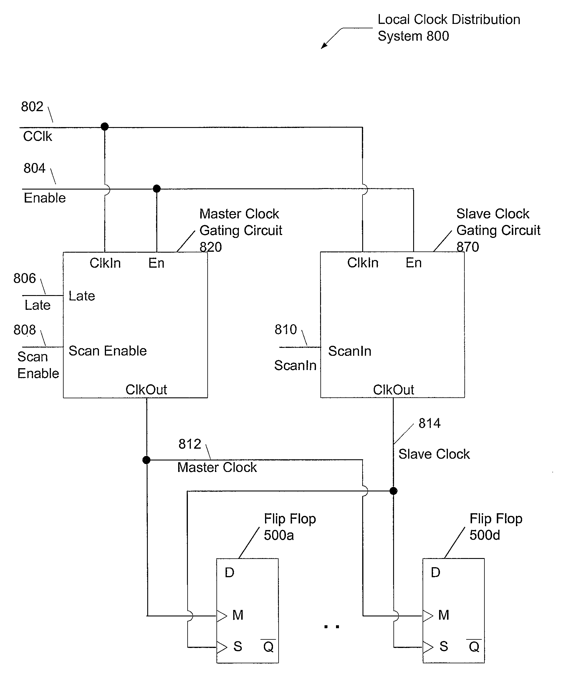
[0013]In another aspect of the invention, a method is provided to distribute split clocks across a semiconductor chip. A master clock signal is generated that is different from a slave clock signal. A delay is selected, wherein the delay determines an additional amount of time the master clock signal transitions after the slave clock signal transitions. Flip-flop circuits receive the master clock signal on a master latch clock input and receive the slave clock signal on a slave latch clock input. This clock distribution may allow a timing path to have more computation time without increasing the clock cycle time.
[0015]The circuitry receives a delay control signal used to select a delay, wherein the delay determines an additional amount of time the master clock signal transitions after the slave clock signal transitions. The master clock gating circuit conveys the master clock signal to a master latch clock input of a flip-flop circuit, wherein the master clock signal is not conveyed to a slave latch clock input of the flip-flop circuit. The use of the master clock gating circuit on the semiconductor chip may allow a timing path on the semiconductor chip to have more computation time without increasing the clock cycle time.

Problems solved by technology

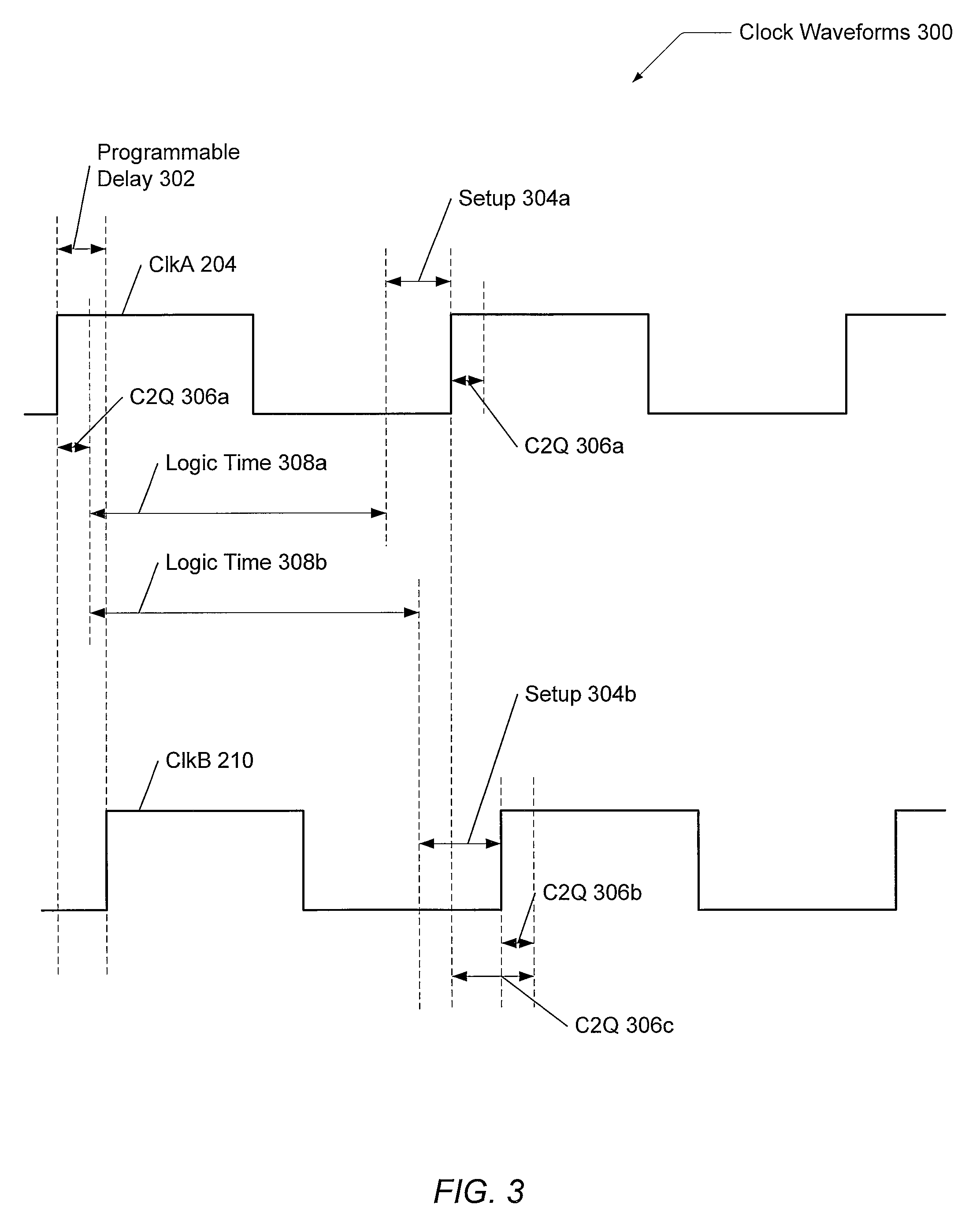
Therefore, setup time, C2Q, skew, and jitter lengthen the clock cycle period, which reduces the operational frequency and performance of the electronic circuit as shown below in the following equation.
However, even if the clock skew and jitter are reduced to a negligible amount, the setup time and C2Q delay still limit the operational frequency as indicated below.
Variations in the models from real behavior and variations in operating temperature and voltage in the post-silicon circuit may cause the skew value to no longer be negligible.
This skew value will decrease the clock cycle period once again, which accordingly, reduces the operational frequency and performance of the circuit.
However, the slave latch of the same flip-flop receives the same delayed clock signal, and thus, the C2Q delay of a second timing path, immediately subsequent to the first timing path, has increased.
However, the increased C2Q delay in the second timing path both reduces the value TLogic reduces the opportunities to utilize the delayed clock in post-silicon in order to optimize timing paths and increase performance.

Method used


Image

  • Programmable sample clock for empirical setup time selection
  • Programmable sample clock for empirical setup time selection
  • Programmable sample clock for empirical setup time selection

Examples


Embodiment Construction

[0030]In the following description, numerous specific details are set forth to provide a thorough understanding of the present invention. However, one having ordinary skill in the art should recognize that the invention may be practiced without these specific details. In some instances, well-known circuits, structures, techniques, and transistor sizing methods have not been shown in detail to avoid obscuring the present invention.

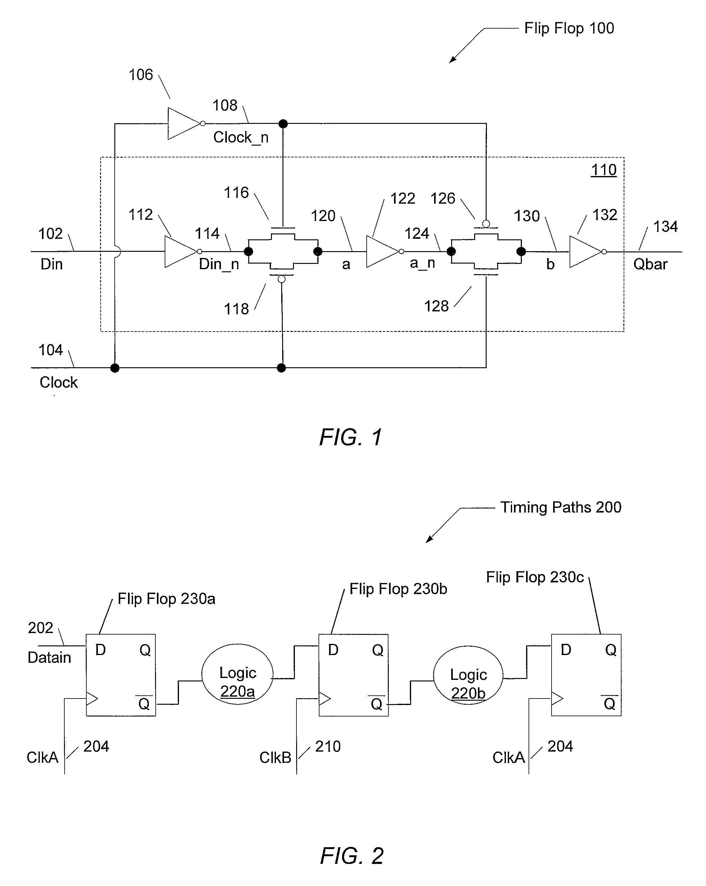
[0031]Referring to FIG. 1, one embodiment of a flip-flop circuit 100 is shown. This particular embodiment is a positive-edge triggered flip-flop comprising pass-gates, or transmission gates, to implement a master latch and a slave latch. One skilled in the art knows other embodiments may include a negative-edge triggered design, and the master-slave configuration may be implemented with other transistor topologies such as sense amps, C2MOS topology, dynamic circuits, differential inputs, and other design choices. A clock signal is received by clock line 104...


PUM


Abstract

A system and method for efficient improvement of timing analysis for faster processor designs with negligible impact on die-area. Rather than provide a single clock to flip-flop circuits on a semiconductor chip, split clocks are used. A flip-flop receives a master clock signal for a master latch and receives a separate slave clock signal for a slave latch. Master and slave clock gater circuits are coupled to a global clock distribution system and the local flip-flops. The master clock gater circuit receives a delay control signal used to select a delay, wherein the selected delay determines an additional amount of time the master clock signal transitions after the slave clock signal transitions. The use of the delayed master clock on the semiconductor chip may allow a timing path to have more computation time without increasing the clock cycle time. Further, the delay may be chosen to fix timing paths in post-silicon.

Description

BACKGROUND OF THE INVENTION[0001]1. Field of the Invention[0002]This invention relates to electronic circuits, and more particularly, to setup time selection for a sequential element.[0003]2. Description of the Relevant Art[0004]Performance of electronic circuits is dependent on the operating frequency of the clock. The duration of a clock cycle period is determined by the amount of time required by combinatorial logic between sequential elements, such as latches and flip-flops, to perform a computation or operation. Also, the clock cycle period is lengthened by the overhead of sequential elements and clock uncertainties. The overhead of sequential elements includes the setup time and the propagation delay clock-to-output (C2Q). Clock uncertainties include clock skew, which is the difference in time a clock signal takes to reach two different sequential elements, and clock jitter, which is the variation of a clock waveform edge from an expected predetermined threshold. Therefore, se...

Claims


Application Information

Patent Timeline
Patent Type & Authority Patents(United States)
IPC IPC(8): H03K19/00H03K3/289G06F7/38
CPCH03K3/0375H03K3/35625
Inventor NAFFZIGER, SAMUEL D.
Owner MEDIATEK INC
Learn More