Multilayer transformer component

a transformer and multi-layer technology, applied in the direction of transformer/inductance details, basic electric elements, coils, etc., can solve the problems of increasing characteristic variation and the risk of output signal characteristics varying

Active Publication Date: 2010-08-10
MURATA MFG CO LTD
View PDF9 Cites 10 Cited by
  • Summary
  • Abstract
  • Description
  • Claims
  • Application Information

AI Technical Summary

Benefits of technology

[0013]To overcome the problems described above, preferred embodiments of the present invention provide a multilayer transformer component having a structure which does not cause a difference in the inductance value between a primary-side coil and a secondary-side coil, and which maintains desired characteristics regardless of a mounting direction of the component.
[0020]In addition, by connecting the first external electrode and the second external electrode to one of differential lines and connecting the third external electrode and the fourth external electrode to the other differential line, the multilayer transformer component according to a preferred embodiment of the present invention can function as a choke coil which has a desired characteristic to remove noise.
[0022]Since the multilayer transformer component according to a preferred embodiment of the present invention is configured so as not to cause a difference in inductance value between the primary-side coil and the secondary-side coil, an insertion loss characteristic does not differ depending on the mounting direction of the multilayer transformer component. This results in an advantage that the desired operation characteristics are ensured regardless of the mounting direction.

Problems solved by technology

When the multilayer transformer component 100 is used as a balun transformer, there is a risk that characteristics of an output signal differ depending on the mounting direction and a characteristic variation increases.

Method used


Image

  • Multilayer transformer component
  • Multilayer transformer component
  • Multilayer transformer component

Examples


Embodiment Construction

[0041]Preferred embodiments of the present invention will be described below with reference to the drawings.

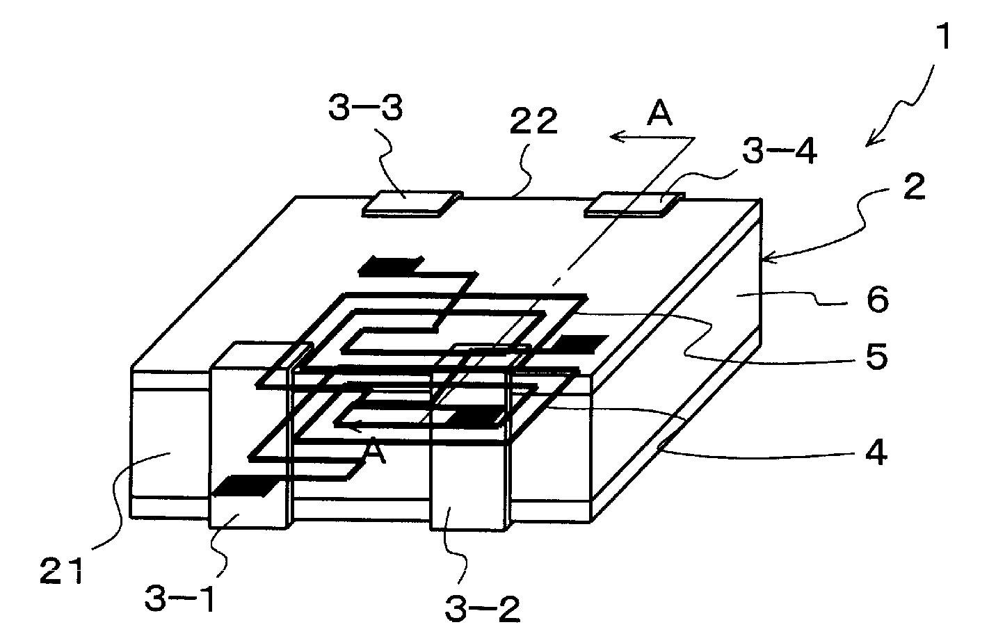
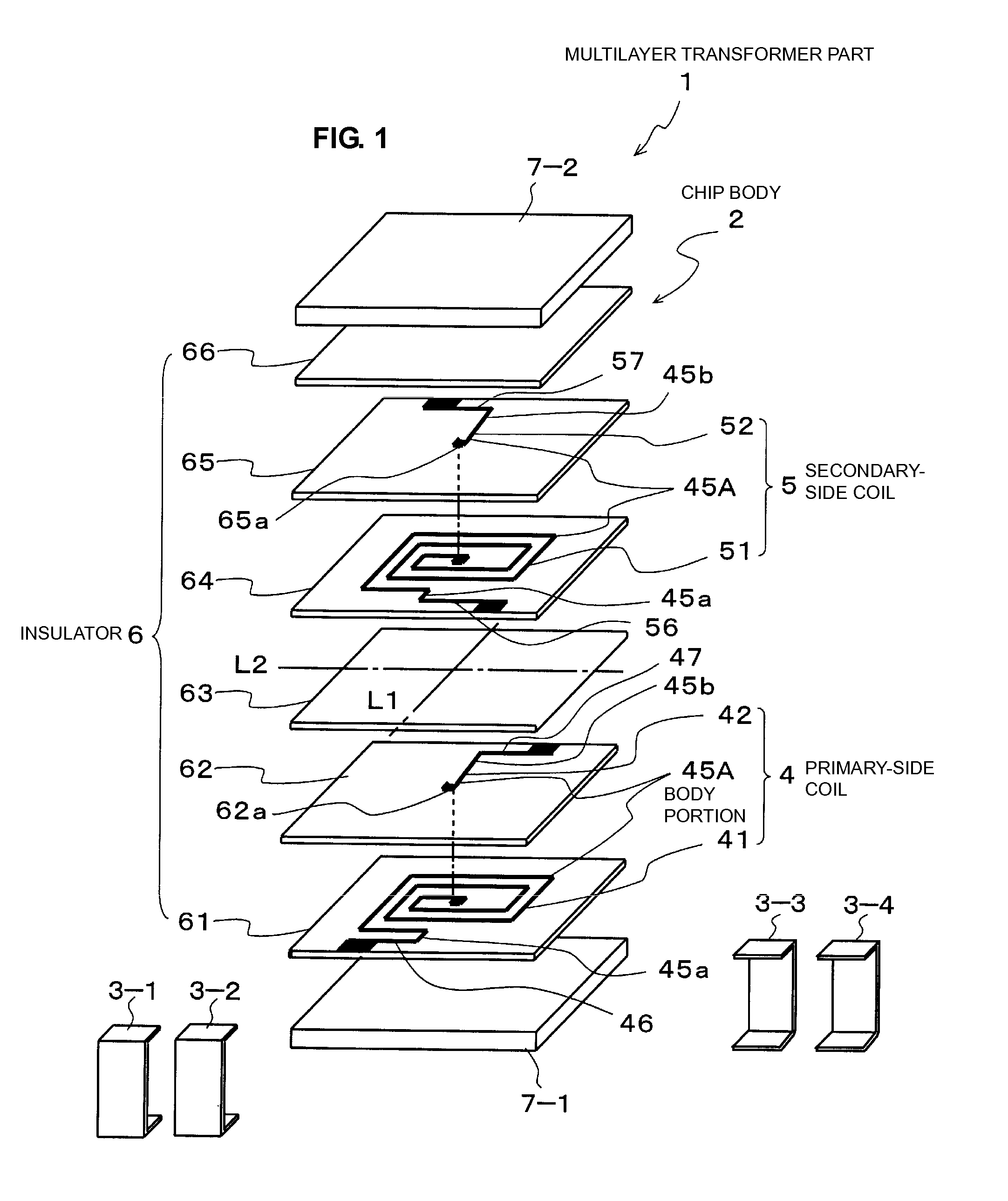
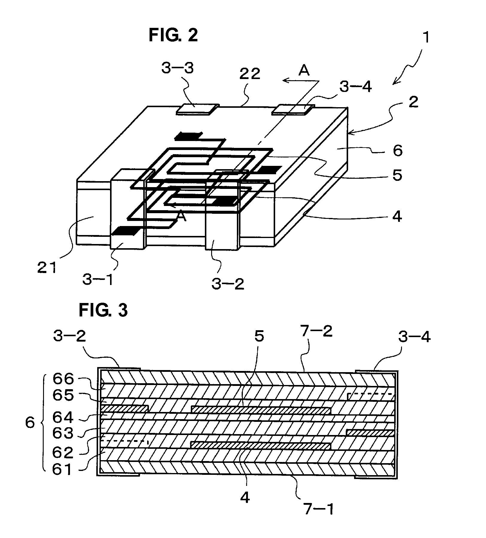
[0042]FIG. 1 is an exploded perspective view illustrating a multilayer transformer component according to a preferred embodiment of the present invention. FIG. 2 is a perspective view of the multilayer transformer component, the view illustrating a primary-side coil and a secondary-side coil in a see-through view. FIG. 3 is a sectional view taken along a line A-A in FIG. 2.

[0043]As illustrated in FIGS. 1 and 2, a multilayer transformer component 1 includes a chip body 2 and first to fourth external electrodes 3-1 to 3-4.

[0044]The chip body 2 includes a primary-side coil 4 and a secondary-side coil 5 that are layered within an insulator 6.

[0045]As illustrated in FIGS. 1 and 3, the insulator 6 is defined by insulating layers 61 to 66. The primary-side coil 4 and the secondary-side coil 5 are provided in predetermined ones of the insulating layers 61 to 66 by patterning, and the ...


PUM

PropertyMeasurementUnit
shapeaaaaaaaaaa
sizesaaaaaaaaaa
densityaaaaaaaaaa

Abstract

A multilayer transformer component includes a chip body including a primary-side coil and a secondary-side coil, and first to fourth external electrodes. The primary-side coil includes a body portion, a first lead, and a second lead, and the secondary-side coil includes a body portion, a third lead, and a fourth lead. A first projection and a second projection of each body portion are arranged to lie substantially on a linear line. The first lead and the fourth lead are arranged to be line-symmetrical with respect to a center line which is arranged at an approximate center between respective distal ends of the first projection and the second projection, and which is perpendicular or substantially perpendicular to an overlying direction of the primary-side and secondary-side coils. The second lead and the third lead are also arranged to be line-symmetrical with respect to the center line.

Description

BACKGROUND OF THE INVENTION[0001]1. Field of the Invention[0002]The present invention relates to a multilayer transformer component used as, e.g., a balun transformer and a common-mode choke coil.[0003]2. Description of the Related Art[0004]Demands for smaller sizes and higher density have increased in the field of transformer components. To meet these demands, a multilayer transformer component is proposed which is formed by, e.g., photolithography capable of performing microfabrication (see, for example, Japanese Unexamined Patent Application Publication No. 2005-158975).[0005]FIG. 16 is a perspective view of a known multilayer transformer component, the view illustrating coil portions in a see-through manner, and FIGS. 17A and 17B are plan views illustrating connection states of external electrodes and coils.[0006]As illustrated in FIG. 16, a multilayer transformer component 100 includes a primary-side coil 101 and a secondary-side coil 102 that are disposed in an insulator 110 w...

Claims


Application Information

Patent Timeline
Patent Type & Authority Patents(United States)
IPC IPC(8): H01F5/00
CPCH01F19/06H01F27/2804H01F2027/2809
Inventor TOI, TAKAOMIISHIDA, KOSUKEISHIDE, DAISUKEKUDO, KAZUHIDE
Owner MURATA MFG CO LTD
Why Eureka
Try Eureka