
Power control system for a continuous time mobile transmitter

a technology of power control system and mobile transmitter, which is applied in power management, wireless communication, frequency-division multiplex, etc., can solve the problem of not being able to adjust the gain for one time slot based on the gain during the previous time slot, and achieve the effect of not being able to achieve the desired gain correction

Active Publication Date: 2010-08-10
QORVO US INC
View PDF7 Cites 91 Cited by
  • Summary
  • Abstract
  • Description
  • Claims
  • Application Information

AI Technical Summary

Benefits of technology

Enables fast and accurate output power correction during the initial 50 microseconds of each time slot, improving battery life by reducing current consumption and maintaining output power within a predetermined range of the target power.

Problems solved by technology

Thus, the traditional power control systems which require approximately 200 microseconds to remove the amplitude modulation from the detected signal are not suitable for measuring and adjusting the gain of the WCDMA transmitter during the first 50 microseconds of a time slot such that the output power is essentially equal to the target output power.
As such, correcting the gain for one time slot based on the gain during the previous time slot is not desirable.

Method used


Image

  • Power control system for a continuous time mobile transmitter
  • Power control system for a continuous time mobile transmitter
  • Power control system for a continuous time mobile transmitter

Examples


Embodiment Construction

[0018]The embodiments set forth below represent the necessary information to enable those skilled in the art to practice the invention and illustrate the best mode of practicing the invention. Upon reading the following description in light of the accompanying drawing figures, those skilled in the art will understand the concepts of the invention and will recognize applications of these concepts not particularly addressed herein. It should be understood that these concepts and applications fall within the scope of the disclosure and the accompanying claims.

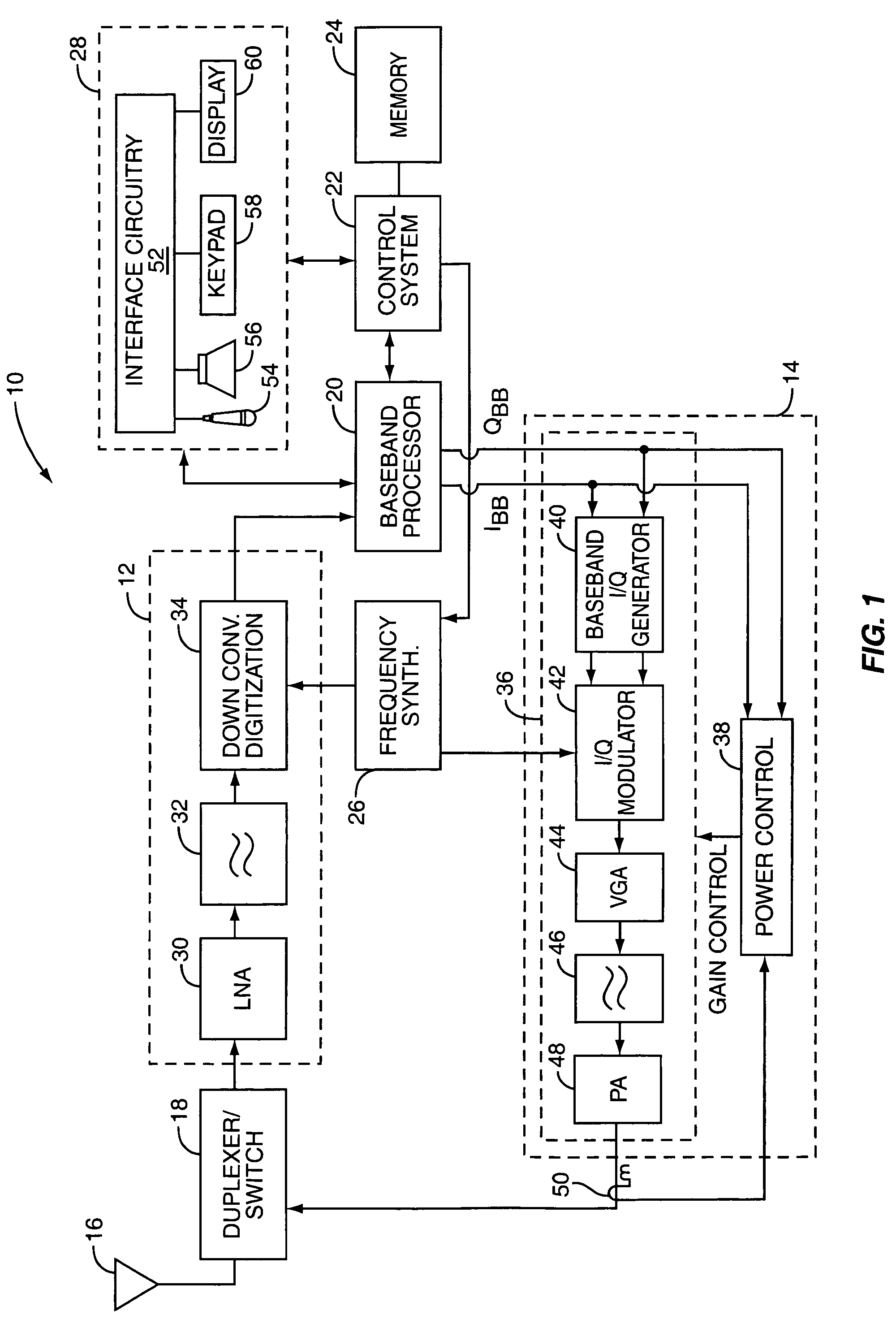
[0019]The present invention is preferably incorporated into a mobile terminal 10, such as a mobile telephone, a personal digital assistant, or the like, operating according to the Wideband Code Division Multiple Access (WCDMA) transmit scheme. However, while the present invention is described with respect to a WCDMA mobile terminal, the present invention is equally applicable to any continuous time transmit system.

[0020]The basic ...


PUM


Abstract

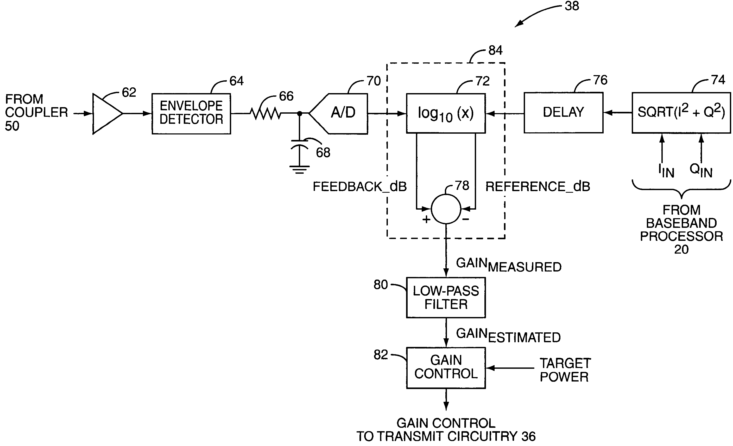
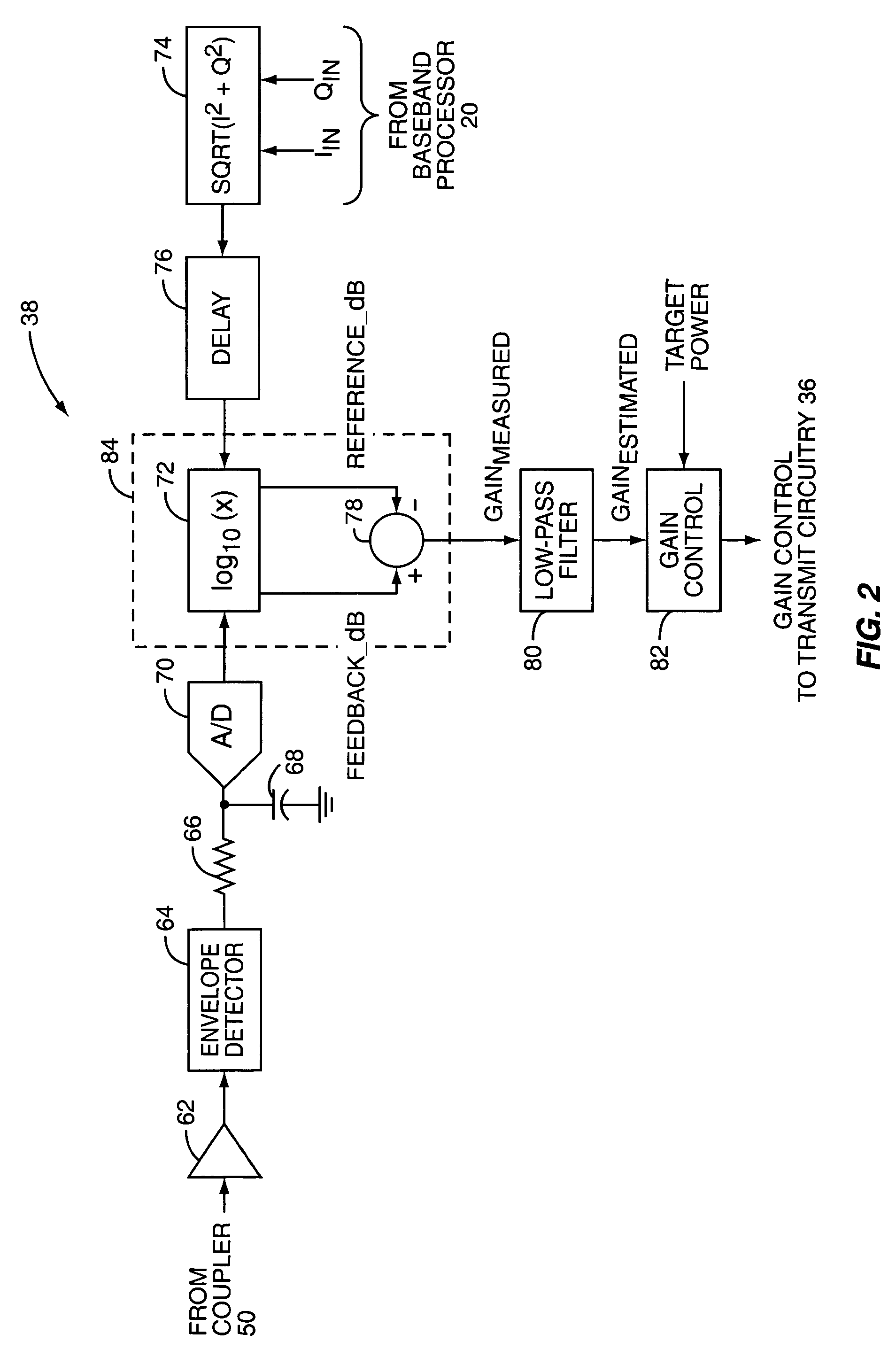
Power control circuitry is provided for controlling an output power of a transmitter of a mobile terminal operating according to a continuous time transmit scheme such as Wideband Code Division Multiple Access (WCDMA). Transmit circuitry processes a quadrature baseband signal to provide a radio frequency transmit signal. The radio frequency transmit signal is coupled to the power control circuitry via a coupler and processed to provide a feedback amplitude signal. The power control circuitry operates to remove an amplitude modulation component from the feedback signal using a reference amplitude signal generated from the quadrature baseband signal, thereby providing a measured gain signal of the transmit circuitry. Based on the measured gain signal and a target output power, the power control circuitry operates to control a gain of the transmit circuitry such that the output power of the transmit circuitry is within a predetermined range about the target output power.

Description

FIELD OF THE INVENTION[0001]The present invention relates to output power control for a mobile terminal, and more particularly relates to output power control in a mobile terminal operating according to a continuous time transmit scheme such as Wideband Code Division Multiple Access (WCDMA).BACKGROUND OF THE INVENTION[0002]As with any other mobile terminal, there is a desire to increase the battery-life of mobile terminals operating according to a continuous time communication scheme, such as Wideband Code Division Multiple Access (WCDMA). One method of increasing the battery-life is to decrease current consumption of the transmitter during low power operation by decreasing the bias current. Changing the bias current of the transmitter also changes the gain, and thus the power step, of the transmitter. In order to achieve a target output power, it is desirable to have a power control system for correcting the gain of the transmitter after a change in bias current.[0003]Traditional p...

Claims


Application Information

Patent Timeline
Patent Type & Authority Patents(United States)
IPC IPC(8): H04K1/02
CPCH03F1/0205H03F3/24H03G3/3042H04L27/362H04W52/52H03F2200/102H03F2200/451
Inventor KHLAT, NADIMBAUDER, RUEDIGER
Owner QORVO US INC
Learn More