
Image forming apparatus with variable photoconductor charging and variable developing bias voltage

a photoconductor and charging technology, applied in the field of image forming apparatus, can solve the problems of difficult stably detecting fog with accuracy, easy generation of fog, and difficult situation, and achieve the effect of accurately determining conditions, preventing fog generation, and easy generation

Inactive Publication Date: 2010-08-10
SHARP KK
View PDF9 Cites 0 Cited by
  • Summary
  • Abstract
  • Description
  • Claims
  • Application Information

AI Technical Summary

Benefits of technology

The present invention provides a technique for accurately predicting fog generated after printing at a low toner coverage ratio is continued. The technology also determines a condition where fog is easily generated without requiring extra cost and time. An image forming apparatus is used to form an image by an electrophotographic process, and a controller controls the charging unit, developing unit, and toner supply unit based on a determined target value of a charging potential or a developing bias voltage. When the absolute value of the determined target value exceeds a prescribed value, the controller controls replacement of a prescribed amount of toner in the developing unit to prevent fogging. This technology allows for accurate prediction and prevention of fogging, without requiring extra cost or time.

Problems solved by technology

From this fact, it is estimated that when the same toner is retained in a developing unit, a kind of deterioration occurs to the toner, thus causing the fog.
However, since the fog is a phenomenon in which the toner is extremely thinly applied to a non-image area, it is difficult to stably detect the fog with accuracy.
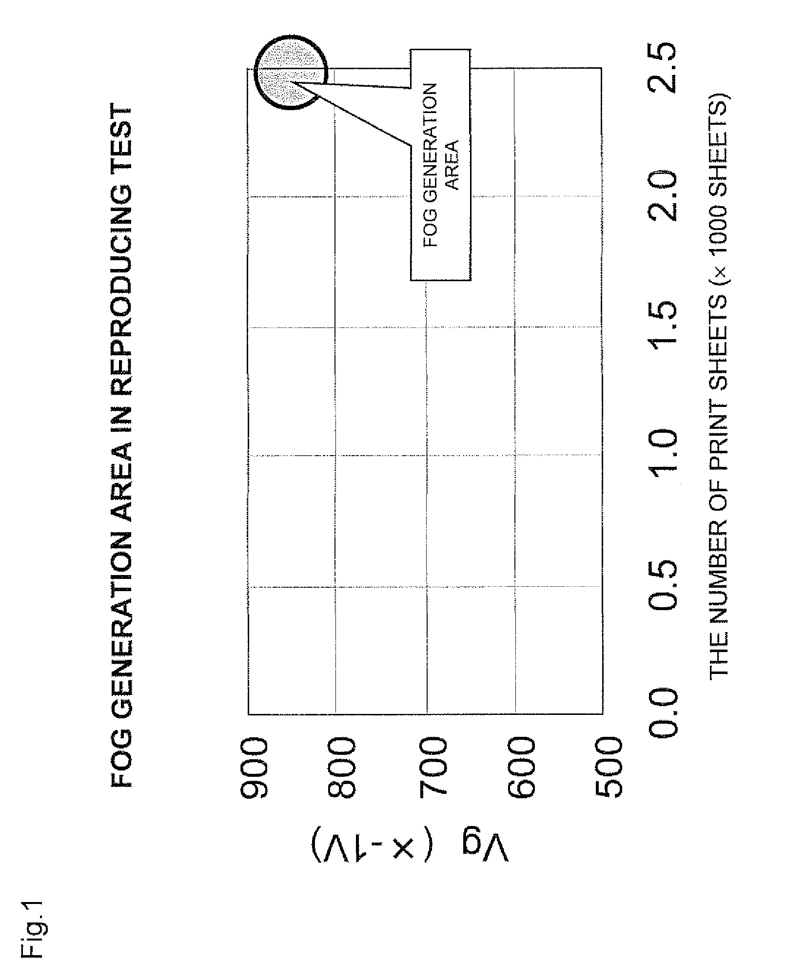
As a result, it is found that an image density adjustment process control executed so as to stabilize the image density makes an absolute value of the charging potential of the photoconductor large, thus leading to a circumstance where the fog is easily generated.
However, in a case where the charging potential is controlled to stabilize the image density when the printing at a low toner coverage ratio is continued as described above, the fog is easily generated.

Method used


Image

  • Image forming apparatus with variable photoconductor charging and variable developing bias voltage
  • Image forming apparatus with variable photoconductor charging and variable developing bias voltage
  • Image forming apparatus with variable photoconductor charging and variable developing bias voltage

Examples


Embodiment Construction

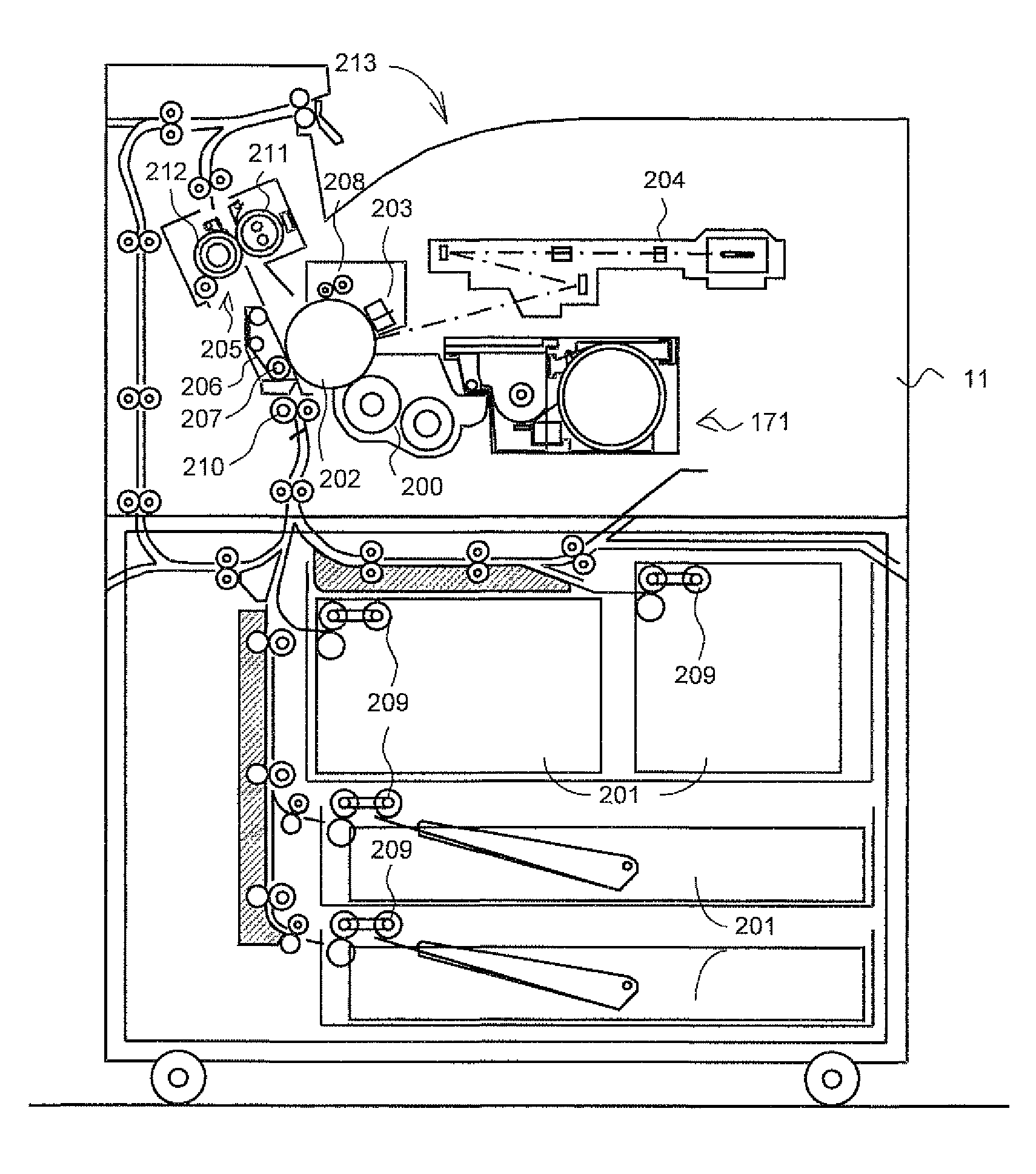
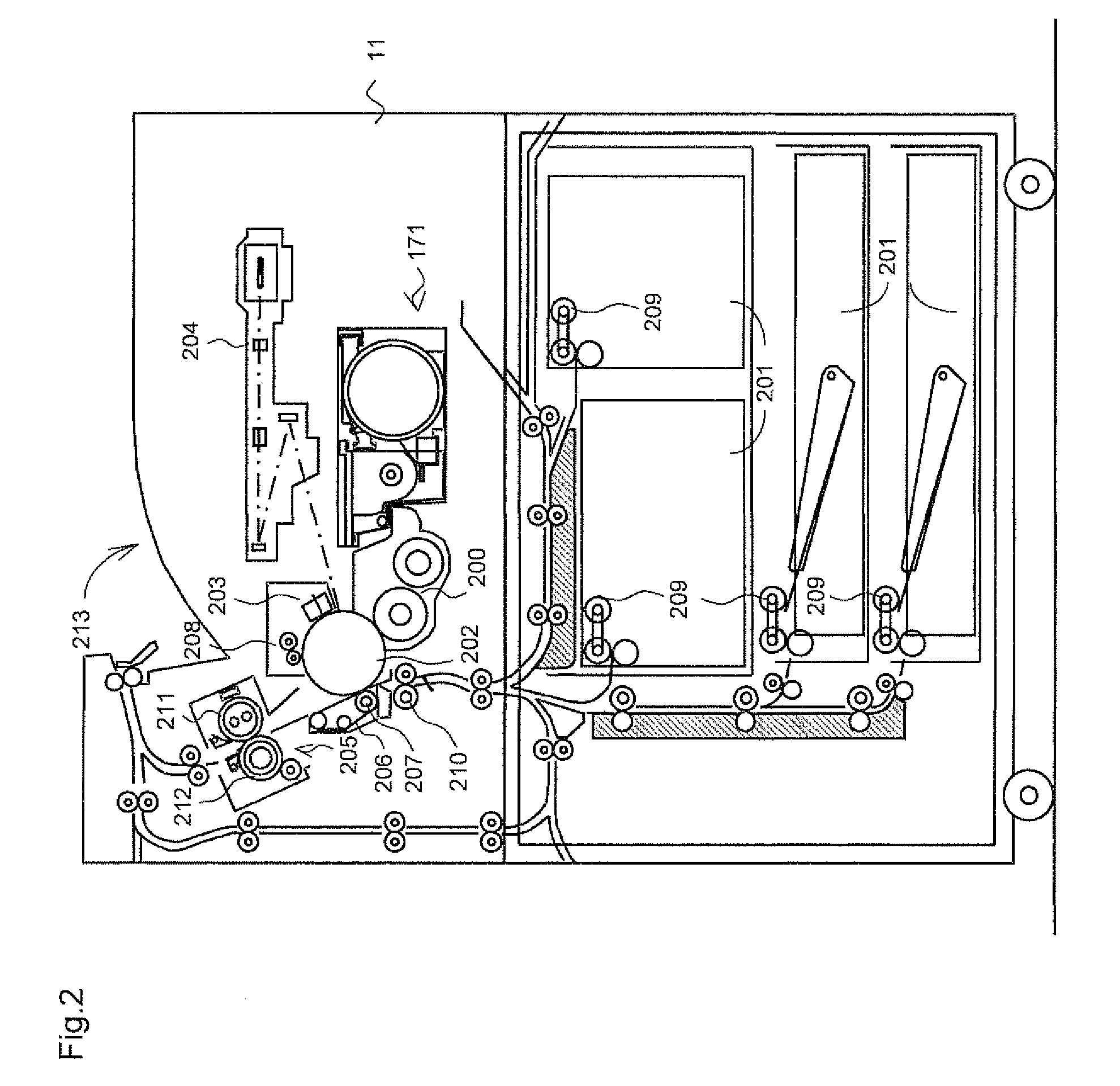
[0024]The system, type, and structure of the photoconductor, the charging unit, the developing unit, the toner supply unit, the developing bias power supply section, which configure the image forming section, are not particularly limited, provided that they can be applied to the image forming apparatus of an electrophotographic system. The controller may be realized, by executing a control program showing a procedure of the processing by, for example, a microcomputer or a CPU. However, the controller is not limited thereto, and, for example may be realized only by a circuit as hardware.

[0025]Preferred embodiments will be explained hereunder.

[0026]The image forming apparatus may further include: a density measuring section for measuring a density of the formed image, wherein when a prescribed opportunity comes, said controller may activate the image forming section to form an image of a pattern having the prescribed amount of a toner, may activate the density measuring section to mea...


PUM


Abstract

An image forming apparatus including: an image forming section for forming an image, the image forming section including a photoconductor, a charging unit, a developing unit, a toner supply unit which supplies a toner to said developing unit, and a developing bias power supply section which supplies a developing bias voltage to said developing unit; and a controller that activates said image forming section, determines a target value of a charging potential of said photoconductor and / or a developing bias voltage, for forming the image, and controls the charging unit and / or the developing bias power supply section in accordance with a determined result, wherein when an absolute value of the determined target value of the charging potential or an absolute value of the determined developing bias voltage is larger than a prescribed value, said controller controls replacement of a prescribed amount of a toner in the developing unit.

Description

CROSS-REFERENCE TO RELATED APPLICATION[0001]This application is related to Japanese application No. 2007-102984 filed on Apr. 10, 2007 whose priority is claimed under 35 USC §119, the disclosure of which is incorporated by reference in its entirety.BACKGROUND OF THE TECHNOLOGY[0002]1. Field of the Technology[0003]The technology relates to an image forming apparatus capable of controlling a charging potential of a photoconductor and a developing bias voltage in an electrophotographic process, and having a function of adjusting a density of a formed image.[0004]2. Description of the Related Art[0005]When an image with a low toner coverage ratio, namely, an image having few parts where toner is adhered out of an entire area of a print image, is printed continuously, it is known that a granular “fog” (phenomenon that the toner is adhered to a white background part where the toner is not supposed to be adhered) is generated eventually. Although a cause of this type of fog is not clarifie...

Claims


Application Information

Patent Timeline
Patent Type & Authority Patents(United States)
IPC IPC(8): G03G15/08
CPCG03G15/0266G03G15/065G03G15/0822G03G15/5062
Inventor NISHIMURA, YASUHIROINO, TOSHIAKITSUJI, AKIKO
Owner SHARP KK
Learn More