Modular cooling system

a cooling system and module technology, applied in the direction of liquid fuel engine components, rotary piston liquid engines, lubricating pumps, etc., can solve the problems of specialized use and failure to deliver the performance of the system designed, and achieve the effect of increasing the outlet pressure of the compressor

Inactive Publication Date: 2010-08-17
BLOMQUIST MIKE
View PDF16 Cites 10 Cited by
  • Summary
  • Abstract
  • Description
  • Claims
  • Application Information

AI Technical Summary

Benefits of technology

[0009]An embodiment includes articulated blade attachments at respective blade roots and a preferential weighting of the blades toward respective blade tips operative to increase an outlet pressure of the compressor.

Problems solved by technology

These adaptations generally have only specialized uses and fail to deliver the performance of systems designed from the start to solve a particular class of cooling problems.

Method used


Image

  • Modular cooling system
  • Modular cooling system
  • Modular cooling system

Examples


Embodiment Construction

[0026]The disclosure provided in the following pages describes examples of some embodiments of the invention. The designs, figures, and description are non-limiting examples of certain embodiments of the invention. For example, other embodiments of the disclosed systems and methods may or may not include the features described herein. Moreover, disclosed advantages and benefits may apply to only certain embodiments of the invention and should be not used to limit the disclosed inventions.

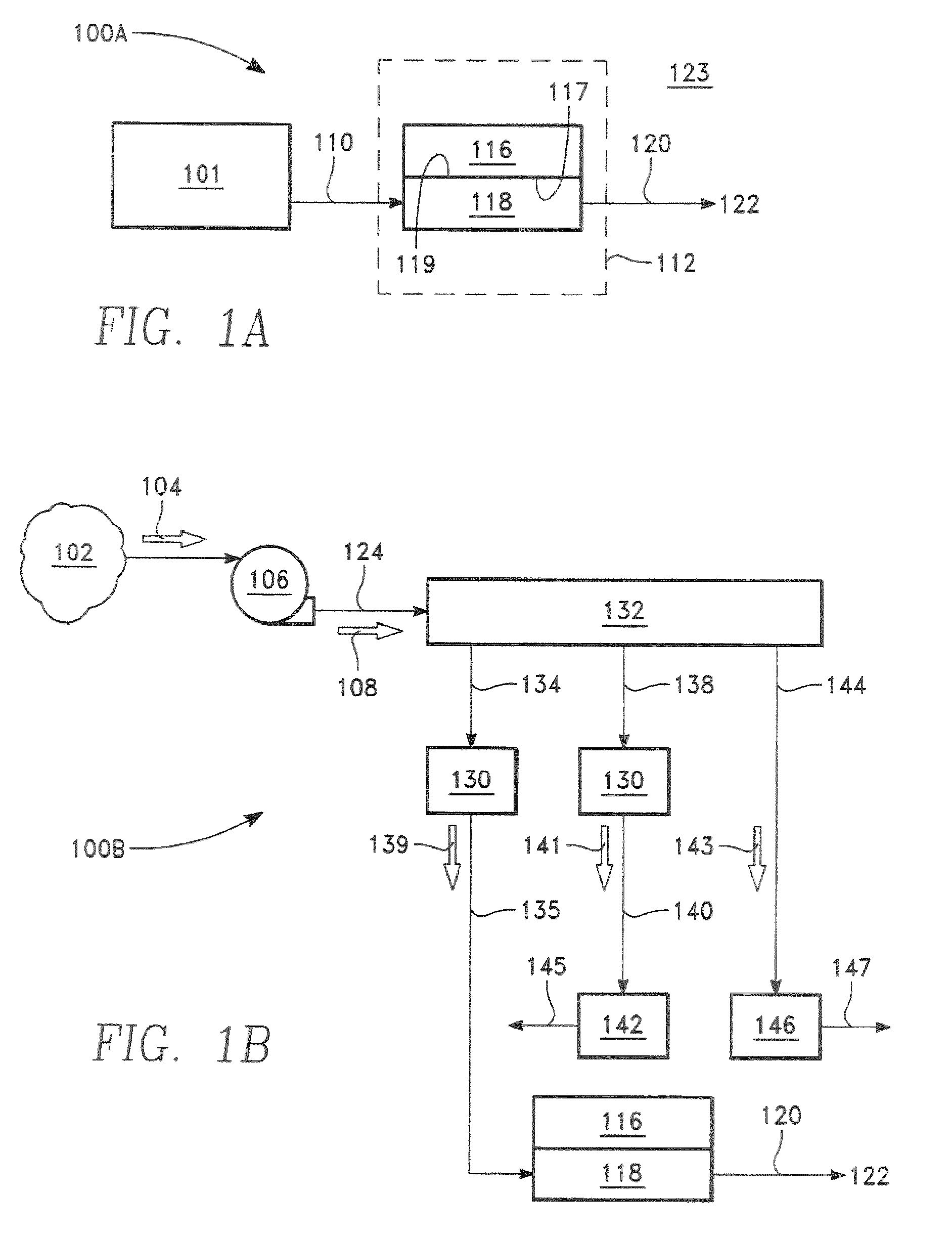
[0027]FIG. 1A shows a cooling system in accordance with the present invention 100A. A heat exchanger or cooler 118 has a heat exchanger surface 117 and an item or device to be cooled 116 has a surface 119. Heat transfer from the item surface to the heat exchanger surface cools the item. In an embodiment, a path for conduction heat transfer exists between the item and heat exchanger surfaces. And, in an embodiment, a physical coupling of the cooler and the item to be cooled establishes contact betwee...


PUM


Abstract

A modular cooling system includes a positive displacement compressor and a microchannel heat exchanger for cooling a heat generating device such as a semiconductor.

Description

PRIORITY CLAIM[0001]This application is a continuation in part of U.S. patent application Ser. No. 12 / 211,060 filed Sep. 15, 2008 and entitled MODULAR COOLING SYSTEM.BACKGROUND OF THE INVENTION[0002]1. Field of the Invention[0003]The present invention relates to a cooling system incorporating a gas compressor and a heat exchanger. In particular, heat absorbed by a gas provides a cooling effect.[0004]2. Discussion of the Related Art[0005]Heat transfer components and in particular heat exchangers have largely been designed for cooling large and / or mechanical items. Such systems have in recent years been adapted to other uses including cooling electronics devices. These adaptations generally have only specialized uses and fail to deliver the performance of systems designed from the start to solve a particular class of cooling problems. The present invention is directed to solving these and other problems associated with cooling items including small and / or non-mechanical items.SUMMARY ...

Claims


Application Information

Patent Timeline
Patent Type & Authority Patents(United States)
IPC IPC(8): F25D23/12F01C1/00F01C5/00
CPCF01C5/06F01C21/0809F04C18/44F25B1/04F28F3/048F28F3/12F28F9/026H01L23/467H01L2924/0002H01L2924/00
Inventor BLOMQUIST, MIKE
Owner BLOMQUIST MIKE
Why Eureka
Try Eureka