Liquid-gas control system for controlled-pressure drilling equipment

A pressure-controlled drilling and control system technology, which is applied to the automatic control system of drilling, drilling equipment, earthwork drilling and production, etc. It can solve problems such as flammable gas escape, pressure control drilling equipment in harsh environment, and pressure control difficulties. To achieve the effect of increasing the outlet pressure

Inactive Publication Date: 2015-02-18
BEIJING MECC HYDRAULIC
View PDF12 Cites 2 Cited by
  • Summary
  • Abstract
  • Description
  • Claims
  • Application Information

AI Technical Summary

Problems solved by technology

[0004] Pressure control drilling equipment is used in harsh environments, for example: there may be flammable gas escaping from the downhole, the wellhead pressure may be high, due to the start-up and shutdown of the mud pump, and the movement of the drilling tool, the bottom-hole pressure may fluctuate rapidly due to different well types and drilling fluids. Larger, making pressure control difficult

Method used


Image

  • Liquid-gas control system for controlled-pressure drilling equipment
  • Liquid-gas control system for controlled-pressure drilling equipment
  • Liquid-gas control system for controlled-pressure drilling equipment

Examples


Embodiment 1

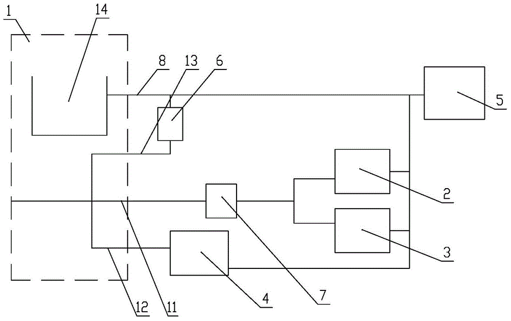
[0034] This embodiment provides a liquid gas control system for managed pressure drilling equipment, such as figure 1 As shown, the liquid and gas control system includes a central controller, a power source 1, a throttle valve control part 2 connected to the power source 1, a hydraulic control flat gate valve control part 5, an air control flat gate valve control part 3 and an oil return pump system Air-operated flat gate valve control part 4. The central controller is connected with the throttle valve control part 2, the air-controlled flat gate valve control part 3 and the air-controlled flat gate valve control part 4 of the oil return pump system.

[0035] Wherein, the power source 1 includes a compressed air processing device and an oil storage device. The compressed air processing device includes three branches separated by the compressed air source through the stop valve and the gas safety valve, the first branch 11 of which is connected to the throttle valve control p...


PUM


Abstract

The invention discloses a liquid-gas control system for controlled-pressure drilling equipment, relates to the technical field of drilling equipment, and aims to solve the problems of inaccuracy in controlling the annular pressure of a well in the conventional drilling process. The liquid-gas control system for the controlled-pressure drilling equipment provided by the invention comprises a power source, and a throttling valve control component, a hydraulic control flat plate gate valve control component, a pneumatic control flat plate gate valve control component and an oil return pump system pneumatic control flat plate gate valve control component which are connected with the power source. Accurate control of the annular pressure of the well is realized in a combination way of pneumatic control and hydraulic control. Moreover, one branch of compressed gas is connected to an oil outlet pipeline of an oil storage device through a liquid-gas pump, so that the outlet pressure of liquid can be effectively raised.

Description

technical field [0001] The invention relates to the technical field of drilling equipment, in particular to a liquid-gas control system for pressure-managed drilling equipment. Background technique [0002] During the drilling of oil and gas wells, if the formation pore pressure is greater than the pressure of the drilling fluid in the wellbore annulus, the formation fluid will flow into the wellbore. Damage to personnel and equipment. The traditional drilling method uses a high-density drilling fluid system to keep the wellbore hydrostatic column pressure greater than the formation pore pressure even when the drilling fluid stops circulating. However, when the formation pore pressure-fracture pressure window is narrow, drilling begins The pressure generated after the fluid circulation may exceed the fracture pressure of the formation, resulting in the collapse of the well wall, and under the action of the pressure difference, the drilling fluid will enter the formation and...

Claims


Application Information

Patent Timeline
Patent Type & Authority Applications(China)
IPC IPC(8): E21B44/00
CPCE21B21/08E21B21/10
Inventor 卢山张钦
Owner BEIJING MECC HYDRAULIC
Why Eureka
Try Eureka