Eureka AIR delivers breakthrough ideas for toughest innovation challenges, trusted by R&D personnel around the world.

Container and one-way valve assembly for storing and dispensing substances, and related method

a one-way valve and container technology, applied in the direction of liquid transfer devices, liquid handling, closures using stoppers, etc., can solve the problems of clogging the release aperture, affecting the integrity of the product, and unsatisfactory oozing, so as to prevent or limit the waste of substances, the effect of limiting the degradation of substances

Inactive Publication Date: 2010-08-17
MAEJ LLC ODONNELL & TESSITORE
View PDF15 Cites 2 Cited by
  • Summary
  • Abstract
  • Description
  • Claims
  • Application Information

AI Technical Summary

Benefits of technology

[0016]One advantage of the present invention is that each device includes a one-way valve assembly that is movably mounted onto a container, such as a squeeze tube-type container, that may be the same as any of numerous containers already in use and thus regulatory approved. The one-way valve assembly includes a piercing portion that pierces a pierceable wall of the container and provides fluid communication of the substance with the one-way valve without having to remove the piercing portion and / or wipe excess substance therefrom after piercing the pierceable wall. The one-way valve assembly limits the substance therein to exposure with the environment including preventing ambient air from being sucked into the container, thus limiting degradation of the substance between usages. The one-way valve also allows dispensing of the substance from a squeeze tube-type container by squeezing the tube to dispense the substance out of the one-way valve assembly while inherently maintaining a dispensing portion of the valve relatively clean and clog free after dispensing and thereby preventing or limiting waste of the substance.

Problems solved by technology

Undesirable oozing and collection of product that can clog the release aperture is common.
Many such prior art dispensers expose the bulk product contained within the dispenser after opening to air, and may expose the bulk product to impurities or other undesirable matter during and / or after application of the product, thereby affecting the integrity of the product remaining in the dispenser and spreading of these impurities with subsequent use of the product or otherwise degrading the product between usages.
Moreover, when the traditional tube is opened, the contents are not only subject to the environment but a quantity of air is normally sucked into the tube.
For example, many products such as liquid lipstick are particularly poorly suited for dispensing by prior art containers.
The liquid lipstick or other product becomes contaminated, evaporates due to air passage losing moisture, and ultimately is unusable if not unsafe before complete utilization of the product.
The tips become contaminated, dirty and sticky or crusty as well as allowing the lipstick or other product to continue to flow when not being used.
Commonly however, the ointment undesirably oozes out of the release aperture upon penetrating the foil seal and the piercing member becomes coated with ointment, thus wasting a portion of the ointment.
Furthermore, the tube does not serve well as an applicator and excess ointment must be wiped from the release aperture before the cover is replaced, adding to waste of the ointment.
However, the increased packaging costs associated with these packets undesirably increases the overall price of the product paid by the consumer.
One drawback associated with prior art dispensers including one-way valves is that the valves are frequently designed to work with mechanical pumps or like actuators that are capable of creating relatively high valve opening pressures.
Squeeze tube-type dispensers, on the other hand, are not capable of creating the necessary valve opening pressures, and therefore such prior art valves do not work effectively with squeeze tubes.

Method used


Image

  • Container and one-way valve assembly for storing and dispensing substances, and related method
  • Container and one-way valve assembly for storing and dispensing substances, and related method
  • Container and one-way valve assembly for storing and dispensing substances, and related method

Examples


Embodiment Construction

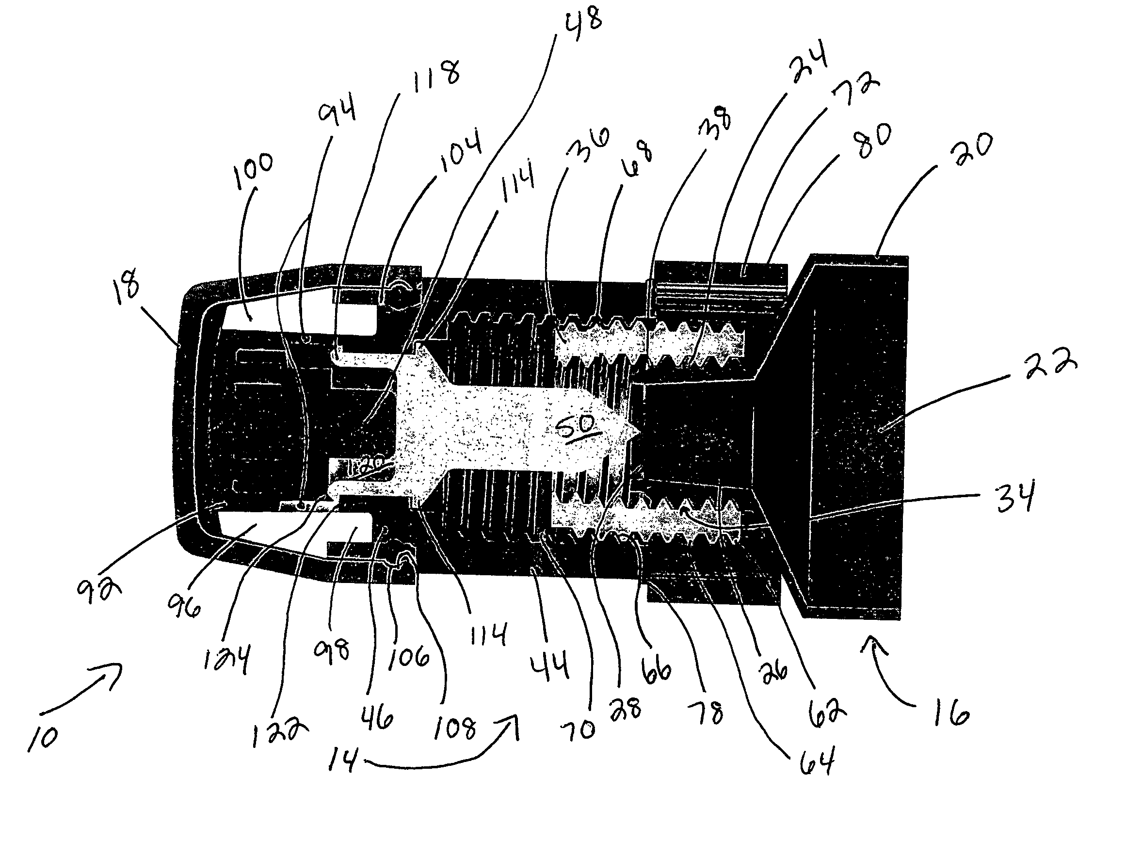
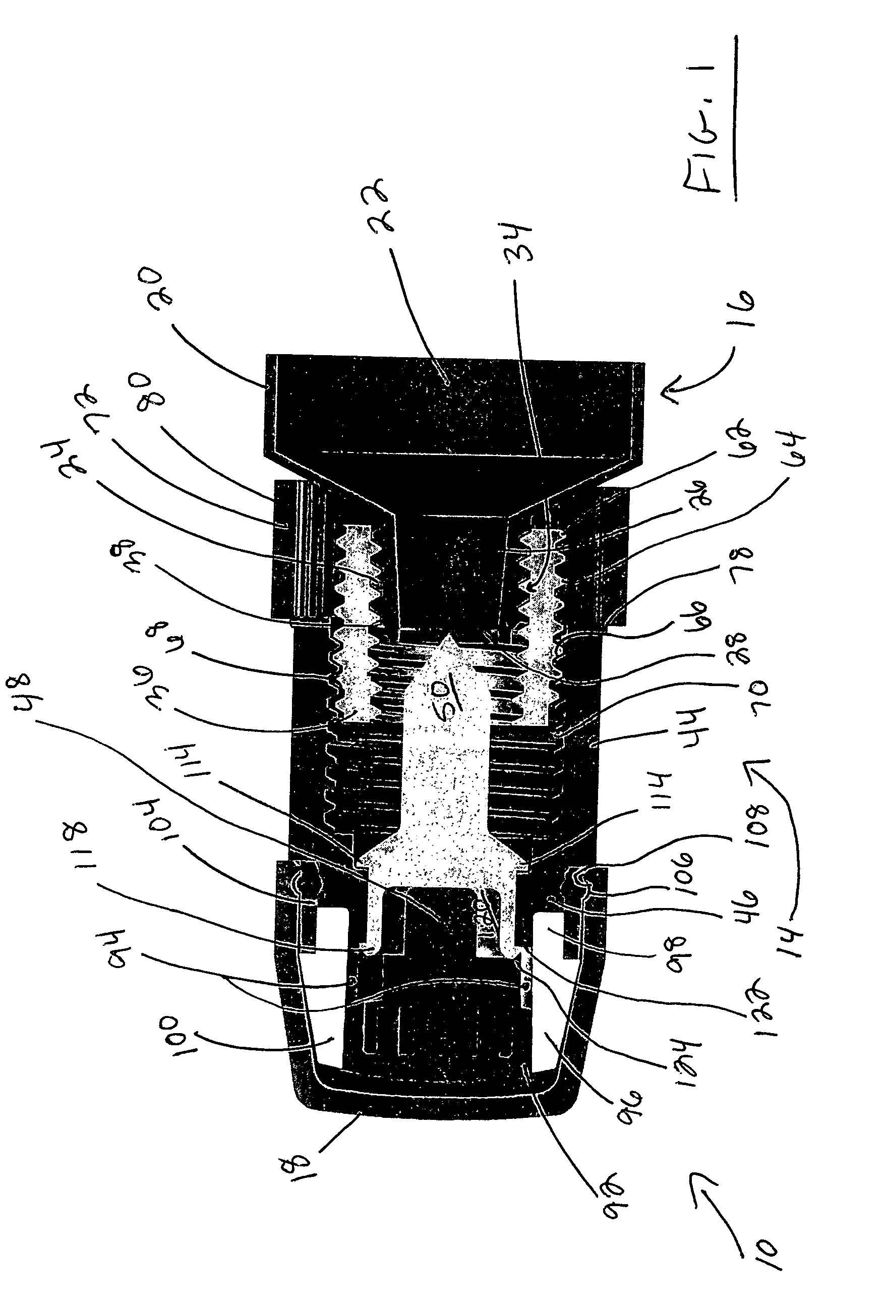
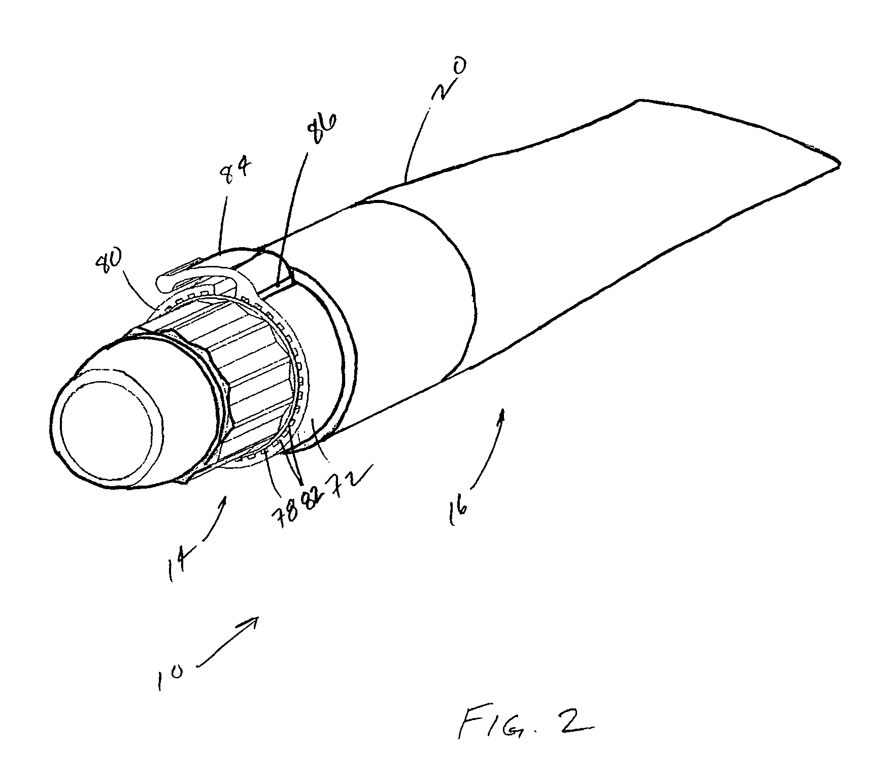
[0038]Referring to FIGS. 1-4, a device including a one-way valve assembly and container embodying the present invention is indicated generally by the reference numeral 10. The device 10 includes a one-way valve assembly 14 that is connectable in fluid communication with a container 16. While the exemplary embodiments illustrate a tubular container, it is understood that any of numerous other container shapes or configurations that are currently known or that later become known equally may be used. A cap 18 is releasably connected to the valve assembly 14 for covering the valve assembly when not in use.

[0039]The container 16 comprises a body 20 defining therein a storage chamber 22 for receiving and storing a substance. The substance includes products that are creamy, pasty, liquid, or other such substance. In an exemplary embodiment, the substance includes any of numerous different types of cosmetics, such as eye and lip treatments, including, for example, lip gloss, eye colors, eye...


PUM


Abstract

A device for storing and dispensing a substance includes a storage chamber for the substance. The container includes a passageway in fluid communication with the storage chamber. The container includes a pierceable wall located on an opposite side of the passageway relative to the storage chamber. The device includes a one-way valve assembly including a piercing portion. At least one of the piercing portion and the pierceable wall is movable relative to the other between a first position wherein the pierceable portion is not piercing the pierceable wall, and a second position wherein the pierceable portion is piercing the pierceable wall allowing the flow of substance from the storage chamber. A removable member is disposed intermediate the valve and the container that prevents movement of at least one of the piercing portion and pierceable wall to the second position until the removable member is removed.

Description

CROSS-REFERENCE TO RELATED APPLICATION[0001]This application claims priority on U.S. Provisional Application No. 60 / 730,520, filed Oct. 26, 2005, entitled “Container and One-Way Valve Assembly for Storing and Dispensing Substances, and Related Method, which is hereby expressly incorporated by reference as part of the present disclosure.FIELD OF THE INVENTION[0002]The invention relates to valves, containers and other apparatus and related method for storing and dispensing substances, such as creamy, liquid, or pasty substances.BACKGROUND OF THE INVENTION[0003]Flexible tubes are used to store a variety of powder, liquid, gel, creamy and pasty products having a broad range of viscosities. Generally, the flexible tubes have a cover which is removed to expose a simple release aperture. As a result, low pressure is required to express the contents therein. Undesirable oozing and collection of product that can clog the release aperture is common. Many such prior art dispensers expose the b...

Claims


Application Information

Patent Timeline
Patent Type & Authority Patents(United States)
IPC IPC(8): B67D1/00B67D99/00
CPCB65D47/205B65D51/227B65D2251/0025B65D2251/0093
Inventor PY, DANIELFLAMENBAUM, MILES J.HARTMAN, ERIC E.HOULE, NATHANIEL
Owner MAEJ LLC ODONNELL & TESSITORE
Why Eureka
Eureka Blog
Learn More