Pole-mounted hook device for electric utility applications

a hook device and utility technology, applied in the field of electric utility tools, can solve the problems of requiring awkward and difficult manipulation of tools, affecting the efficiency of the operation of the utility, and continuously putting the safety of the workers at risk

Inactive Publication Date: 2010-08-17
TAYLOR TODD
View PDF22 Cites 11 Cited by
  • Summary
  • Abstract
  • Description
  • Claims
  • Application Information

AI Technical Summary

Benefits of technology

[0002]Extension devices referred to as “hot sticks” have been used in conjunction with tools to perform various functions on difficult to reach utility devices. Often the utility devices are mounted high on a utility pole, and many carry electric current. Thus, utility workers are continuously in danger while working on utility devices such as power-lines transformers, fuse boxes, and many others. The utility worker uses an extension pole with an attachment portion at its distal end, which allows the utility worker to removably attach a utility tool to the end of the extension and raise the utility tool to the location of a utility device requiring maintenance. Typically, such utility tools have physical components designed to assist in manipulating the utility device in some physical manner while isolating the utility worker from electrical current.

Problems solved by technology

Thus, utility workers are continuously in danger while working on utility devices such as power-lines transformers, fuse boxes, and many others.
However, the tools currently available for performing this task do not provide efficient and easy manipulation of the fuse limiter.
Specifically, the tools require awkward and difficult manipulation in order to perform the various functions associated with removing or installing the fuse limiter.

Method used


Image

  • Pole-mounted hook device for electric utility applications
  • Pole-mounted hook device for electric utility applications
  • Pole-mounted hook device for electric utility applications

Examples


Embodiment Construction

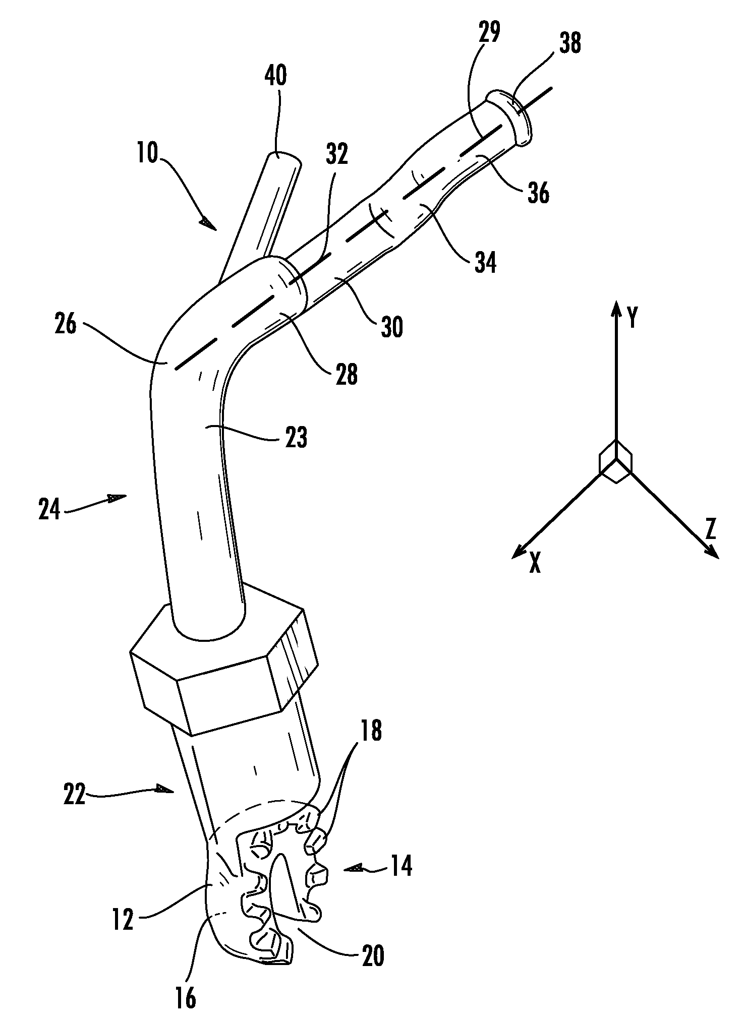
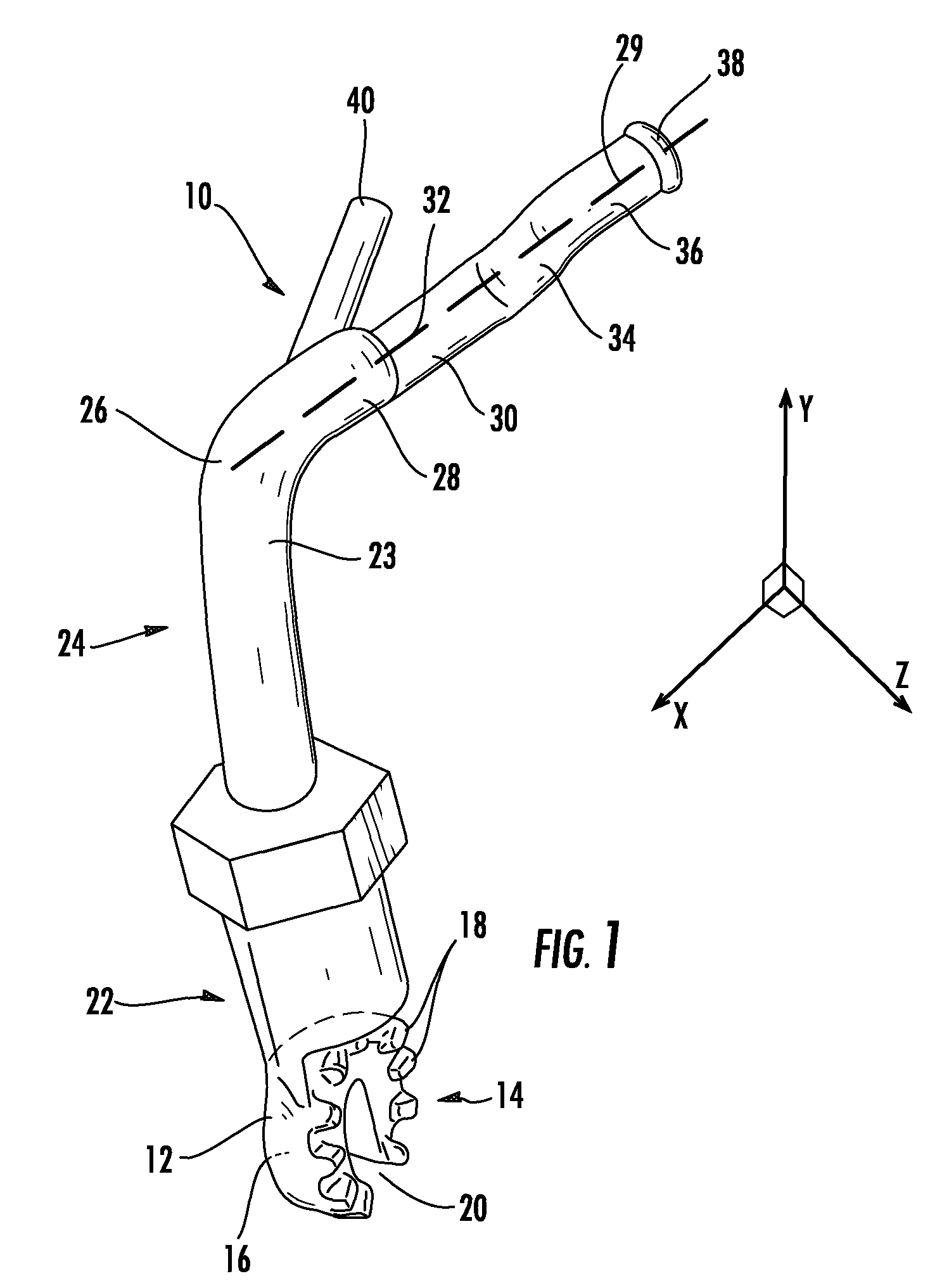
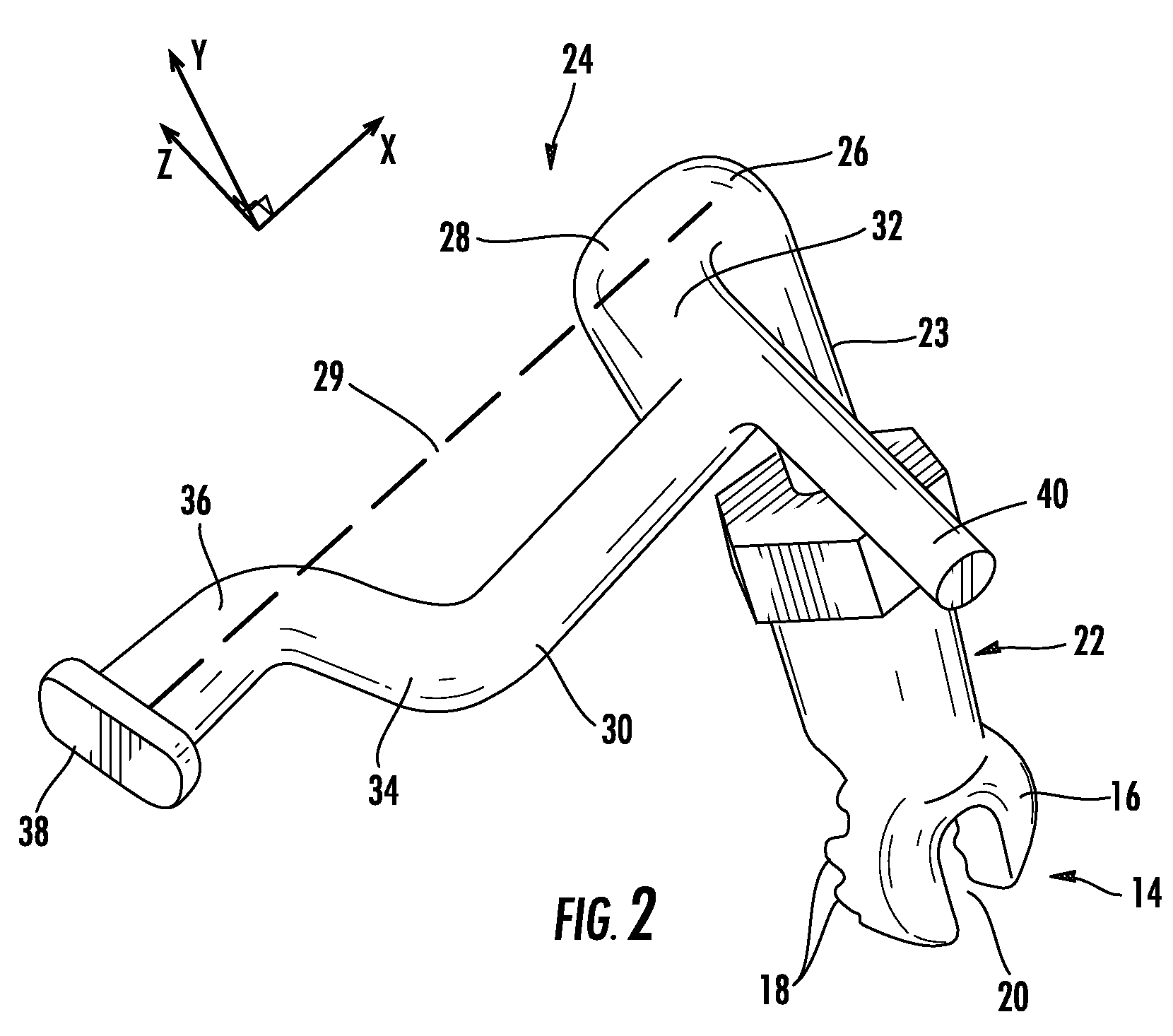
[0016]Perspective views of a hook device 10 for mounting on an extension pole are shown in FIGS. 1 and 2. FIG. 3 shows the hook device 10 from a top plan view. With collective reference to FIGS. 1-3, the hook device 10 has an attachment portion 12, substantially in the form of a cylindrical prism having two opposite substantially flat sides 14 and 16 the surface of the sides defining a device plane, as indicated in FIG. 1 by the X-Y plane. One side 14 of the attachment portion 12 has a plurality of teeth 18 for coupling with teeth of a receiving portion (not shown) of a mounting pole such as a utility pole also referred to as a “hot stick.” The attachment portion 12 has a fastening aperture 20 removed radially from a center of the attachment portion such that a fastener may be used to couple the attachment portion to the receiving portion of a mounting pole. The fastener may be a nut and bolt combination or other type of fastening apparatus.

[0017]The pole attachment portion 12 is pa...


PUM


Abstract

A hook device for coupling with a universal pole such as a utility pole or hot stick performs a plurality of functions including at least physically engaging a component of a utility device. The hook device has a base having an axis with a pole attachment for coupling with the universal pole. An arm extends from the base along the axis of the base at the arm's upper portion and bends at an elbow at a right angle extending in a forearm, which, together with the axis of the base define a first plane. A hook portion is connected to the forearm and has a geometry in a second plane at the first angle from the axis of the forearm. An end portion is connected to the hook portion and has the same axis as the forearm. A finger is angled from the axis of the forearm at the third angle and angled from the axis of the base at the second angle.

Description

FIELD[0001]This disclosure relates to the field of electric utility tools. More particularly, this disclosure relates to a pole-mounted hook device for electric utility applications and a method for using the same.BACKGROUND AND SUMMARY[0002]Extension devices referred to as “hot sticks” have been used in conjunction with tools to perform various functions on difficult to reach utility devices. Often the utility devices are mounted high on a utility pole, and many carry electric current. Thus, utility workers are continuously in danger while working on utility devices such as power-lines transformers, fuse boxes, and many others. The utility worker uses an extension pole with an attachment portion at its distal end, which allows the utility worker to removably attach a utility tool to the end of the extension and raise the utility tool to the location of a utility device requiring maintenance. Typically, such utility tools have physical components designed to assist in manipulating t...

Claims


Application Information

Patent Timeline
Patent Type & Authority Patents(United States)
IPC IPC(8): A47F13/06B25J1/00
CPCH01H31/127H02G1/04H01H33/006H01H85/0208
Inventor TAYLOR, TODD
Owner TAYLOR TODD
Why Eureka
Try Eureka