Arc detection and handling in radio frequency power applications

a radio frequency power and arc detection technology, applied in the field of radio frequency power delivery, can solve the problems of not being able to detect and respond to changes in plasma impedance, damage to the surface of workpieces or even to the processing equipment itself, charge buildup and eventual electrical breakdown of dielectric films on the surface, etc., to achieve better yield, improve process quality and throughput, and improve sensitivity.

Active Publication Date: 2006-10-26
AES GLOBAL HLDG PTE LTD
View PDF95 Cites 56 Cited by
  • Summary
  • Abstract
  • Description
  • Claims
  • Application Information

AI Technical Summary

Benefits of technology

[0012] In another embodiment of the invention, an RF power delivery system employs parallel arc detection circuitry. A slow-filtered measurement of a power delivery parameter is used in to compute dynamic arc detection boundaries, in conjunction with one or more user-selected constants that determine sensitivity of the detection circuitry. A fast-filtered value of the power delivery parameter is compared to the computed detection boundaries in order to detect occurrence of an arcing condition. In this way, a flat pass band is created between the cut-off of...

Problems solved by technology

While RF power supplies are typically well protected against sudden changes in load impedance, they generally are not designed to detect and respond to changes in plasma impedance caused by arcing within a process chamber.
As a result, an RF power supply may continue to feed energy into incipient arcs that develop within a plasma process, which in turn may cause serious damage to the surface of a workpiece or even to the processing equipment itself.
In a reactive sputtering process, arcing often results from charge buildup and eventual electrical breakdown on the surface of dielectric films deposited on the sputtering target or chamber walls.
Only recently has it been recognized, however, that occasional arcing occurs in RF processes as well, and that for sensitive film properties or geometries this RF arcing can be equally as damaging.
Other factors include defects in the reactor or chamber hardware, degr...

Method used


Image

  • Arc detection and handling in radio frequency power applications
  • Arc detection and handling in radio frequency power applications
  • Arc detection and handling in radio frequency power applications

Examples


Embodiment Construction

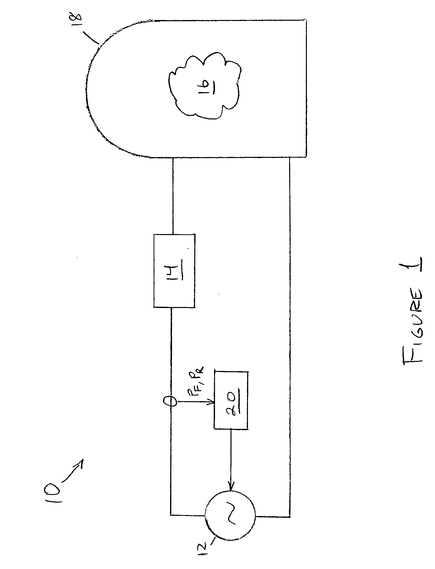
[0017]FIG. 1 illustrates a plasma processing system in accordance with one embodiment of the invention. Processing system 10 comprises RF power generator 12 that delivers RF power through impedance matching network 14 to a plasma 16 within plasma chamber 18. Instantaneous values of forward power PF and reflected power PR are measured at the output of generator 12 and communicated to control logic 20, which controls a disconnection circuit at the output of power generator 12.

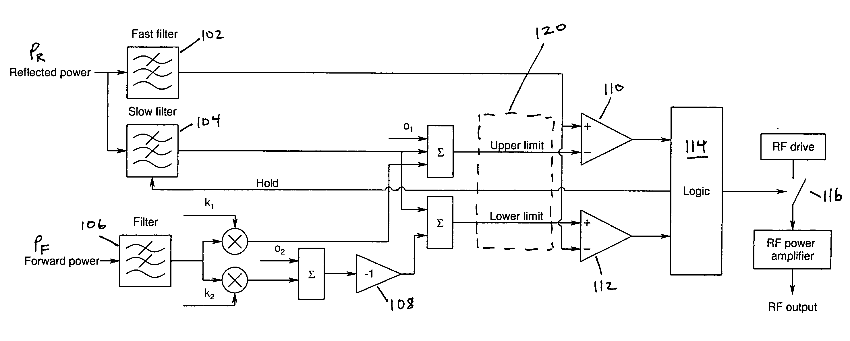
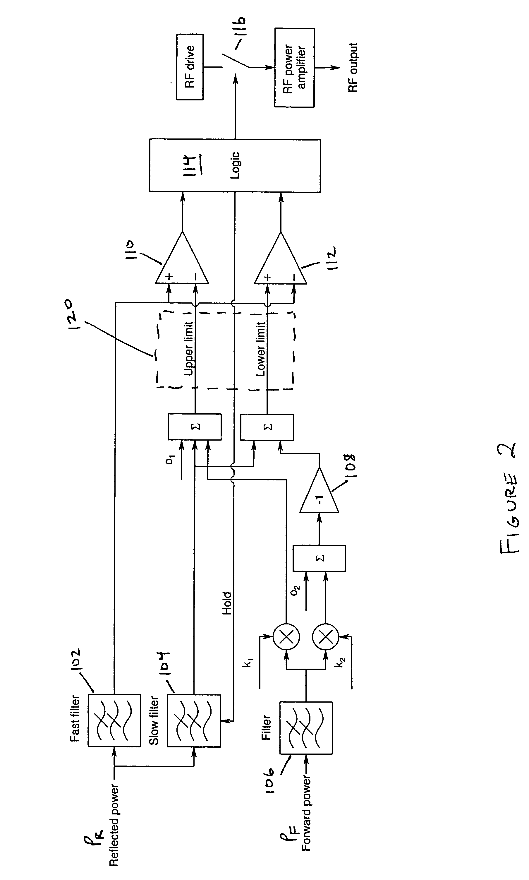
[0018]FIG. 2 illustrates a process and circuitry for arc detection and handling in an RF power delivery application in accordance with one embodiment of the invention. Measurements of forward power PF and reflected power PR are filtered through filters 102, 104, and 106. Absolute offset values O1 and O2, and multipliers k1 and k2, are user-selected inputs that determine the sensitivity of the arc detection circuitry. The sum of offset O1 from slow-filtered reflected power and multiplier k1 applied to filtered fo...


PUM


Abstract

A radio frequency power delivery system comprises an RF power generator, arc detection circuitry, and control logic responsive to the arc detection circuitry. A dynamic boundary is computed about the measured value of a parameter representative of or related to the power transferred from the power generator to a load. A subsequently measured value of the parameter that exceeds the computed dynamic boundary of the parameter indicates detection of an arc. Upon detection of an arc, power delivery from the generator is interrupted or adjusted, or other action is taken, until the arc is extinguished. By employing dynamic computation of arc detection boundaries, the invention allows for arc handling in RF power deliver systems regardless of whether the system has reached a stable power delivery condition.

Description

BACKGROUND OF THE INVENTION [0001] 1. Field of the Invention [0002] This invention relates generally to radio frequency power delivery, and more particularly to the detection and avoidance of arcing in radio frequency powered plasma processes. [0003] 2. Brief Description of the Prior Art [0004] Radio frequency (RF) powered plasma processes are commonly used in the manufacture of semiconductors, flat panel displays, data storage devices, and in other industrial applications. While RF power supplies are typically well protected against sudden changes in load impedance, they generally are not designed to detect and respond to changes in plasma impedance caused by arcing within a process chamber. As a result, an RF power supply may continue to feed energy into incipient arcs that develop within a plasma process, which in turn may cause serious damage to the surface of a workpiece or even to the processing equipment itself. [0005] In DC powered plasma processes, the problem of arcing has...

Claims


Application Information

Patent Timeline
IPC IPC(8): G06F19/00
CPCH01J37/32082H01L21/67069H01J2237/0206H01J37/32174H01L21/3065
Inventor VAN ZYL, GIDEON J.
Owner AES GLOBAL HLDG PTE LTD
Why Eureka
Try Eureka