Huber needle safety enclosure

Active Publication Date: 2010-08-17
CR BARD INC
View PDF74 Cites 47 Cited by
  • Summary
  • Abstract
  • Description
  • Claims
  • Application Information

AI Technical Summary

Benefits of technology

[0030]A further embodiment of the present invention is where the second basic embodiment is modified by having the gripping handle extend to a lower position which is to rest on the skin of the patient and prevent rocking movement of the needle.
[0031]A third basic embodiment of the present invention is directed to a Huber needle safety enclosure which has a Huber needle mounted within a needle housing with this Huber needle having a sharp outer end. A panel unit is composed of a series of edge connected sheet material panels assembled in an enclosing arrangement definin

Problems solved by technology

Because of this ninety degree bend configuration of the needle, removing the needle at the end of the infusion therapy is particularly dangerous to the medical practitioner.
This danger has to do with applying an outward force to the needle, and when the needle is exterior of the port, there is a natural bounce-back of the needle.
As a result, the medical practitioner may be subjected to the same infection that the patient is subjected to.
However, the implanted port has one significant disadvantage and that there is a high degree of needlestick injury during removal of the Huber needle by the practitioner.
In the past, a needlestick injury has been attributed to carelessness on the part of the medical practitioner.
In actuality, carelessness has little to do with needlestick injuries as it is directly related to the difficulty of removing the needle.
Inherently, the procedure of removing of a Huber needle results in bounce-back which comprises a rebounding effect.
This hooking of the needle is due to a snag occurring impeding the removal of the needle from the septum.
When the needle is finally released, the muscles relax and an opposite movement takes place and drives the Huber needle point down into the non-dominant hand of the medical practitioner thus

Method used


Image

  • Huber needle safety enclosure
  • Huber needle safety enclosure
  • Huber needle safety enclosure

Examples


Embodiment Construction

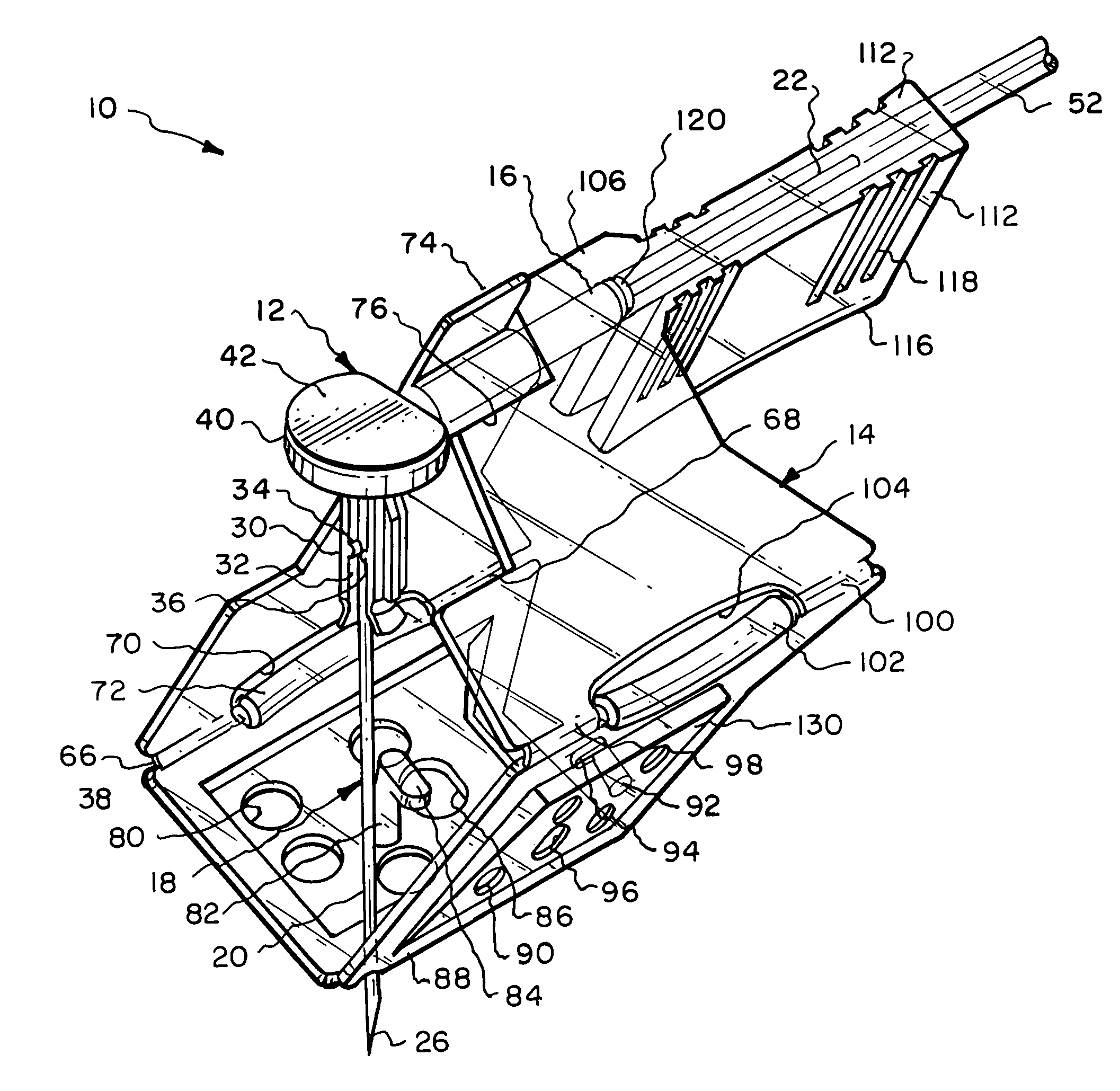
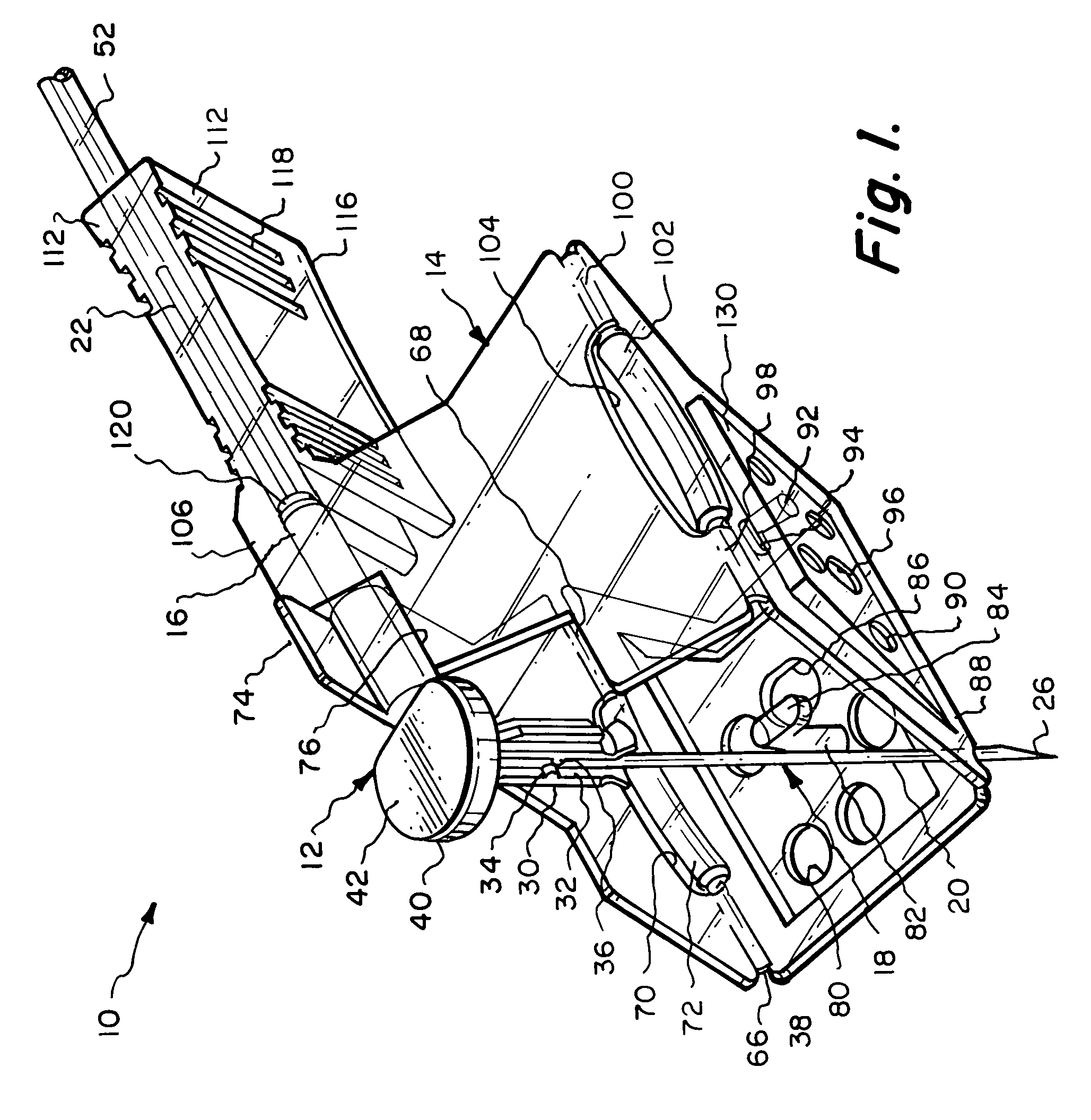
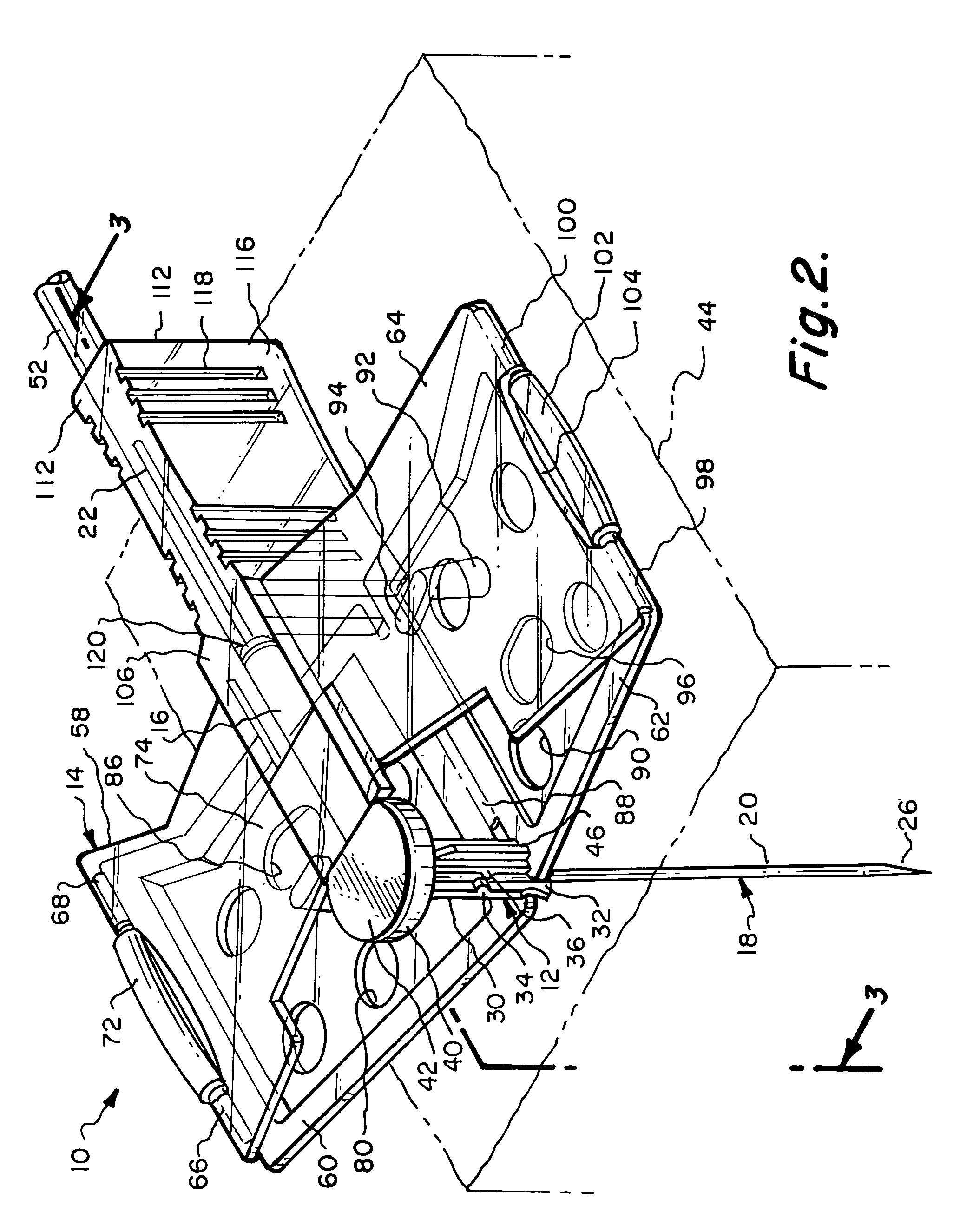
[0047]Referring particularly to the drawings, there is shown the Huber needle safety enclosure 10 of this invention. The safety enclosure 10 includes, generally, a needle housing 12 and a panel unit 14. The needle housing 12 includes an elongated cylindrical hinge tube 16 which is constructed of plastic as well as almost all of the components of this enclosure 10. The only part that is not constructed of plastic will be the Huber needle 18 itself, which will be constructed of metal.

[0048]The Huber needle 18 is in the shape of a right angle and has a fore end 20 and an aft end 22. The fore end 20 is connected to the aft end 22 at a bend 24. The free end of the fore end 20 is formed into a sharpened tip 26. The hinge tube 16 has a through passage 28. The aft end 22 of the Huber needle 18 is located in a close fitting but yet slidable manner within the through passage 28. Integrally connected to the hinge tube 16 at its front end is a sleeve 30. Longitudinally formed within the sleeve ...


PUM


Abstract

A safety enclosure which is designed for a hypodermic needle that is located in the shape of an approximate right angle (Huber needle). A safety enclosure has a needle housing within which the Huber needle is mounted. The needle housing is mounted in conjunction with a panel unit. The panel unit is composed of a series of planar panels which are edge connected together defining an enclosed area. The panel unit can be movable from a basically transverse position to an elongated position. When in the transverse position, the panel unit is to be mounted with adhesive tape onto the skin of a patient with the sharp end of the needle being inserted within the body of the patient. When the panel unit is in the elongated position, the needle is withdrawn from the body of the patient and the sharpened end of the needle is covered by the panels thereby preventing undesired needlestick injury to the medical practitioner that is installing and removing the enclosure.

Description

BACKGROUND OF THE INVENTION[0001]1. Field of the Invention[0002]This invention is directed to a safety enclosure for a hypodermic needle known as a Huber needle and more particularly to improvements over a prior art type of safety enclosure which is defined within U.S. Pat. No. 5,951,522, entitled HYPODERMIC NEEDLE SAFETY ENCLOSURE, issued Sep. 14, 1999.[0003]2. Description of the Related Art[0004]Within the medical field, some patients require the use of a vascular access device as part of his or her care. A vascular access device is used on a patient to provide pain drugs, chemotherapy, antibiotics, antiviral or antifungal drugs as well as for hydration and nutrition. In recent years, there has been a substantial increase in the number of patients with implanted ports. An implanted port requires a special needle to be inserted through the skin of the patient and into the port. The most common type of such a needle includes a ninety degree bend and is commonly referred to as a Hube...

Claims


Application Information

Patent Timeline
IPC IPC(8): A61M31/00
CPCA61M5/158A61M5/3275A61M2005/1581
Inventor HALSETH, THOR R.BARKER, JOHN M.
Owner CR BARD INC
Why Eureka
Try Eureka