Method of operating non-ferrous smelting plant

a smelting plant and non-ferrous technology, applied in the direction of reverberatory furnaces, furnaces, grain treatment, etc., can solve the problems of ineffective operation, two parallel drying and conveying systems are detrimental, and the production amount of non-ferrous metal can be increased, the crushing speed is enhanced, and the effect of easy operation

Active Publication Date: 2010-08-17
JX NIPPON MINING & METALS CORP
View PDF6 Cites 2 Cited by
  • Summary
  • Abstract
  • Description
  • Claims
  • Application Information

AI Technical Summary

Benefits of technology

[0068](1) Only the flux is conveyed in the first system, and only the copper ore is conveyed in the second system. According to a prior art, the flux is conveyed into the drier. This part of the flux is completely replaced with the copper ore. Drying amount of the copper ore in the drier can be increased by approximately 10% (methods (1), (2) and (3) mentioned above). Production amount of non ferrous metal can be increased by approximately 10% in the smelting plant as a whole.
[0069](2) The flux is dried in a ball mill under the frictional heat, which is generated under the normal operation of the ball mill. The flux is additionally dried in a forcible manner by hot air. The silica ore therefore hardly adheres in the ball mill and hence the crushing speed is enhanced (the method (4) mentioned above). The method ((4)) can easily cope with the increase in the ratio of flux / ore.
[0070](3) Hot air hardly leaks outside a ball mill and hence the thermal efficiency of drying is enhanced (the method (5), mentioned above).
[0071](4) When leakage of hot air occurs, the pressure within a ball mill can be controlled by creating a pressure difference between the interior and outside of a ball mill by means of operating an exhaust-gas fan. Blowing-up of ore from an ore-feeding belt can, therefore, be suppressed (the method (6), mentioned above). In addition, a hot-air boosting fan can enhance the drying ability and hence the crushing ability (the method (7), mentioned above).
[0072](5) A gas cooler installed in a bypassing passage according to the prior application can recover the hot air with excessive heat. This excessive heat is utilized for drying and crushing. Thermal energy consumption in the entire smelting plant is, therefore, saved (the method (8) mentioned above).
[0073](6) Damage of a dust collector can be prevented. A dust collecting cloth of a bag filter can be protected (the method (9) mentioned above).

Problems solved by technology

However, these publications are not related to crushing of non-ferrous metal ores or flux.
Generally speaking, in order to dry and convey the ore and the flux at a higher speed, a gas-stream drying apparatus and a belt conveyor must be completely redesigned and rebuilt, which requires a large investment cost.
To redesign a drier, since such factors as the solid / gas ratio and dust collecting capacity must be taken into consideration comprehensively, a number of difficulties arise in the drier reconstruction.
However, the two parallel drying and conveying systems are detrimental in view of complicacy, ineffective operation, excessive capacity, and large investment cost.
When the water content of the silica ore fed to the ball mill increases, that heat is not sufficient for drying it.
In the worst case, crushing is difficult to continue.
Since the drying performance of a conventional ball mill of the silica ore is unsatisfactory, the usual practice has been to mix the crushed silica ore with the copper concentrate and is then dry them again in a drier together.
It can, therefore be said that the drying capacity of a ball mill had not been fully utilized heretofore, thus limiting the amount of the silica ore that could be treated in a ball mill.
As a result, when the crushed silica ore is charged into a drier of copper-concentrate, the drying load of the drier is increased corresponding to the water content of the silica ore, thus limiting the amount of copper concentrate that can be treated.

Method used


Image

  • Method of operating non-ferrous smelting plant
  • Method of operating non-ferrous smelting plant
  • Method of operating non-ferrous smelting plant

Examples


Embodiment Construction

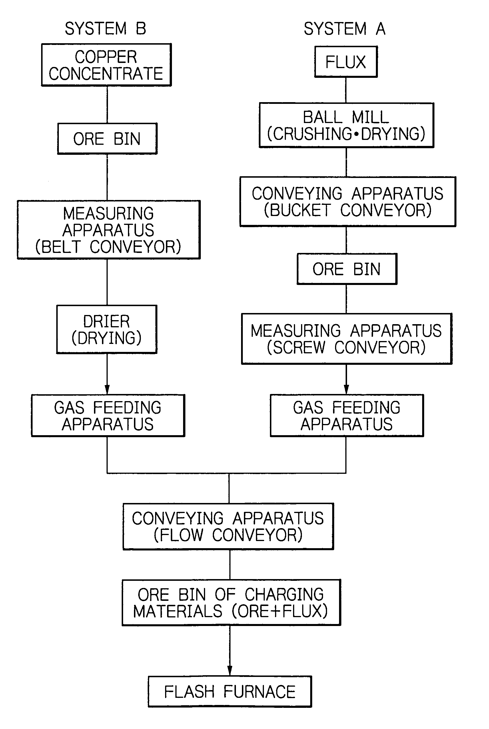
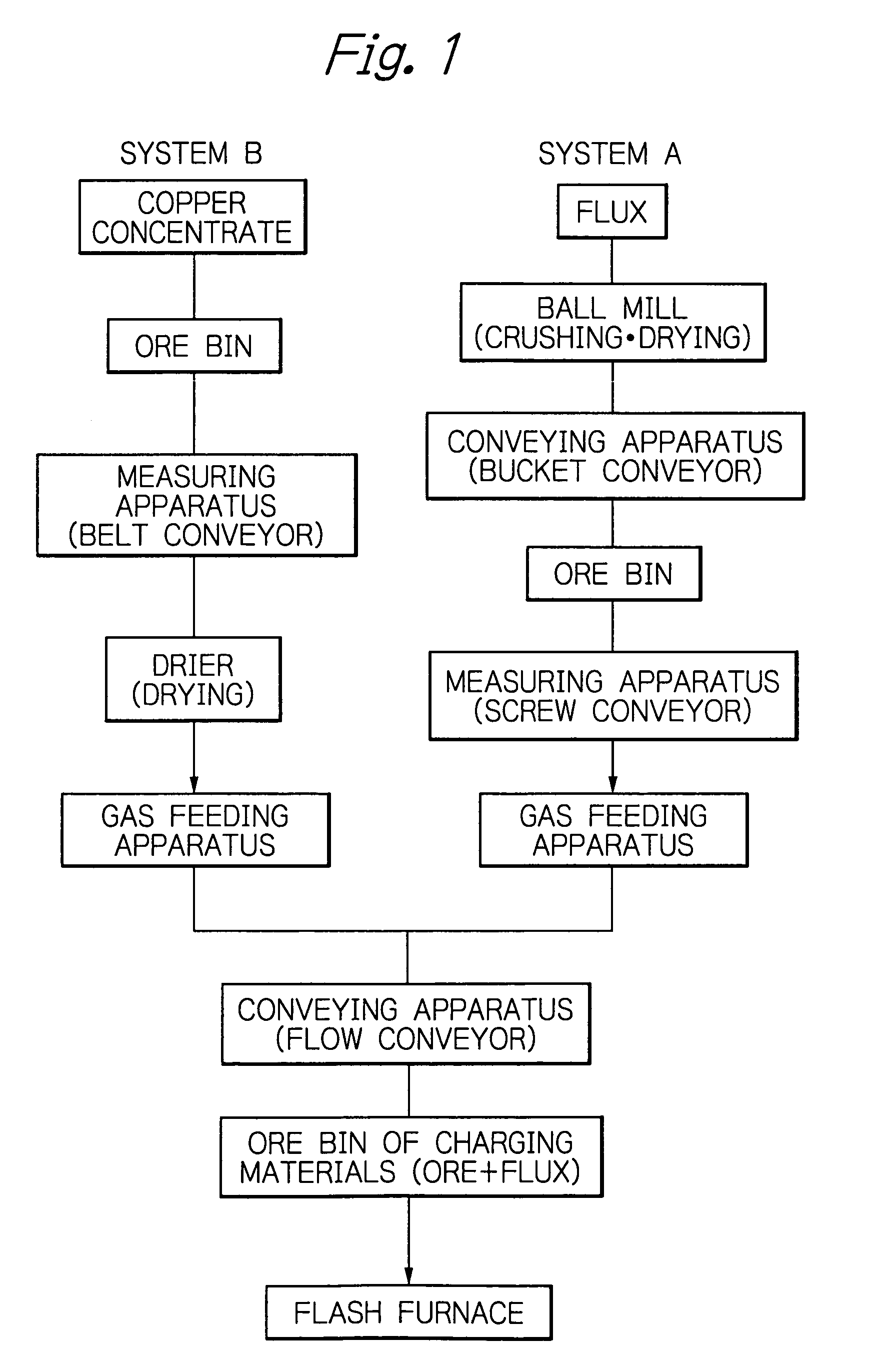
[0039]The operation method according to the present invention is further described with reference to the flow sheet of FIG. 1. In FIG. 1, the first and second systems are denoted by A and B, respectively.

[0040]In the present invention, the copper concentrate and the flux are conveyed through different systems to a location directly before a flash furnace and then charged into the flash furnace. According to the prior art, a predetermined amount of copper concentrate measured and fed from its ore bin and a predetermined amount of the flux measured and fed from its ore bin are conveyed through the same single system, directly before the flash furnace. The flow sheet shown in FIG. 1 corresponds to the operation methods (1) and (2), mentioned above, and are exactly the same as the conveying systems of the present applicant at the present time. In other words, none of reconstruction, modification or change is carried out at all. If necessary, a feeding apparatus of copper ore provided by...


PUM

PropertyMeasurementUnit
temperatureaaaaaaaaaa
particle sizeaaaaaaaaaa
temperatureaaaaaaaaaa

Abstract

In the operation, a flux mainly composed of silica ore and a non-ferrous metal-ore raw-material are charged into a smelting furnace via a conveying system. In order to increase the production amount of the metal, the flux is conveyed and treated through a first system, in which the flux is crushed in a ball mill and dried in the bail mill, and the crushed and dried flux is conveyed directly before the smelting furnace. The non-ferrous metal ore is treated and conveyed through a second system, in which it is dried with a drier and then conveyed directly before the smelting furnace. In the drier of copper concentrate, the flux is not dried at all.

Description

BACKGROUND OF THE INVENTION[0001]1. Field of Invention[0002]The present invention relates to a method for operating a non-ferrous smelting plant, and more particularly to a method for increasing the production amount of non-ferrous metals. In a non-ferrous smelting plant, the raw material, such as copper or nickel sulfide ores or their concentrates, together with a flux mainly composed of silica ore, are introduced into a smelting furnace, such as a flash furnace or a reverberatory furnace. The present invention is hereinafter described mainly with reference to copper smelting by means of a flash furnace.[0003]2. Description of Related Art[0004]The silica ore, which is fed to a copper smelting furnace, such as a flash furnace or a reverberatory furnace, supplies SiO2 that reacts with Fe in the copper ores. Precious metals such as gold and silver, contained in small amounts in the silica ore, are also recovered in the copper smelting process. The silica ore is conveyed from a mine to...

Claims


Application Information

Patent Timeline
Patent Type & Authority Patents(United States)
IPC IPC(8): C22B15/04C22B15/06
CPCC22B1/00C22B15/0006C22B15/0028C22B15/0047C22B15/0097
Inventor NAKAGAWA, KENTAYASUDA, YUTAKASUZUKI, YOSHIAKI
Owner JX NIPPON MINING & METALS CORP
Why Eureka
Try Eureka