Circuit breaker

a circuit breaker and circuit technology, applied in the direction of circuit breaker contacts, circuit breaker switches, relays, etc., can solve the problems of limiting the opening/closing lifetime and wear and tear of contacts, and achieve the effect of high current-carrying performan

Inactive Publication Date: 2010-08-17
MITSUBISHI ELECTRIC CORP
View PDF24 Cites 10 Cited by
  • Summary
  • Abstract
  • Description
  • Claims
  • Application Information

AI Technical Summary

Benefits of technology

[0012]As described above, whereas the present invention pertains to the shuntless current-carrying mechanism superior to mechanically opening / closing lifetime, the circuit breaker that is provided with the movable contacting device having a high current-carrying performance, can be achieved.

Problems solved by technology

The former depends chiefly on wear and damage of its mechanical component.
Meanwhile, the latter is dominated by, in addition to those, wear and tear of contacts, normally being shorter in lifetime than the former.
Regarding the damage of the mechanical component, a fatigue burnout of parts that perform electrical connections by means of a flat stranded copper wire or a sheet metal that provides flexibility (hereinafter referred to as shunt), is particularly a major cause that limits the opening / closing lifetime.

Method used


Image

  • Circuit breaker
  • Circuit breaker
  • Circuit breaker

Examples


embodiment 1

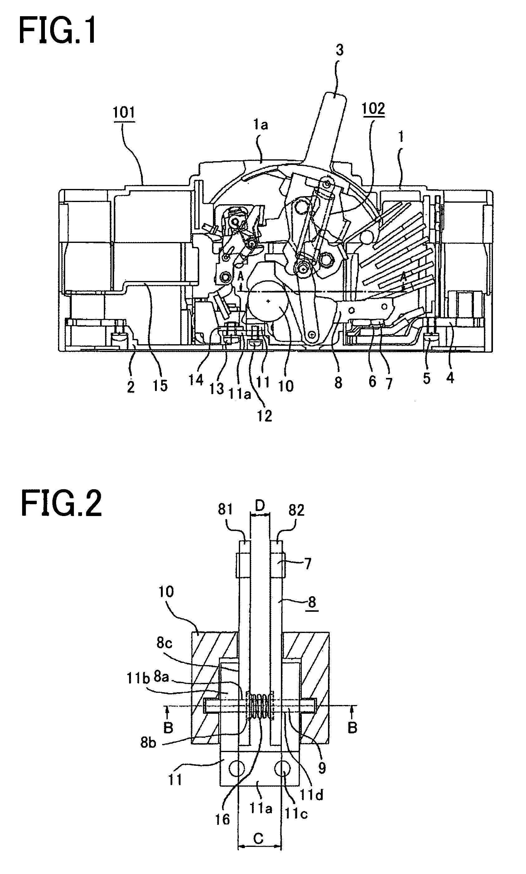
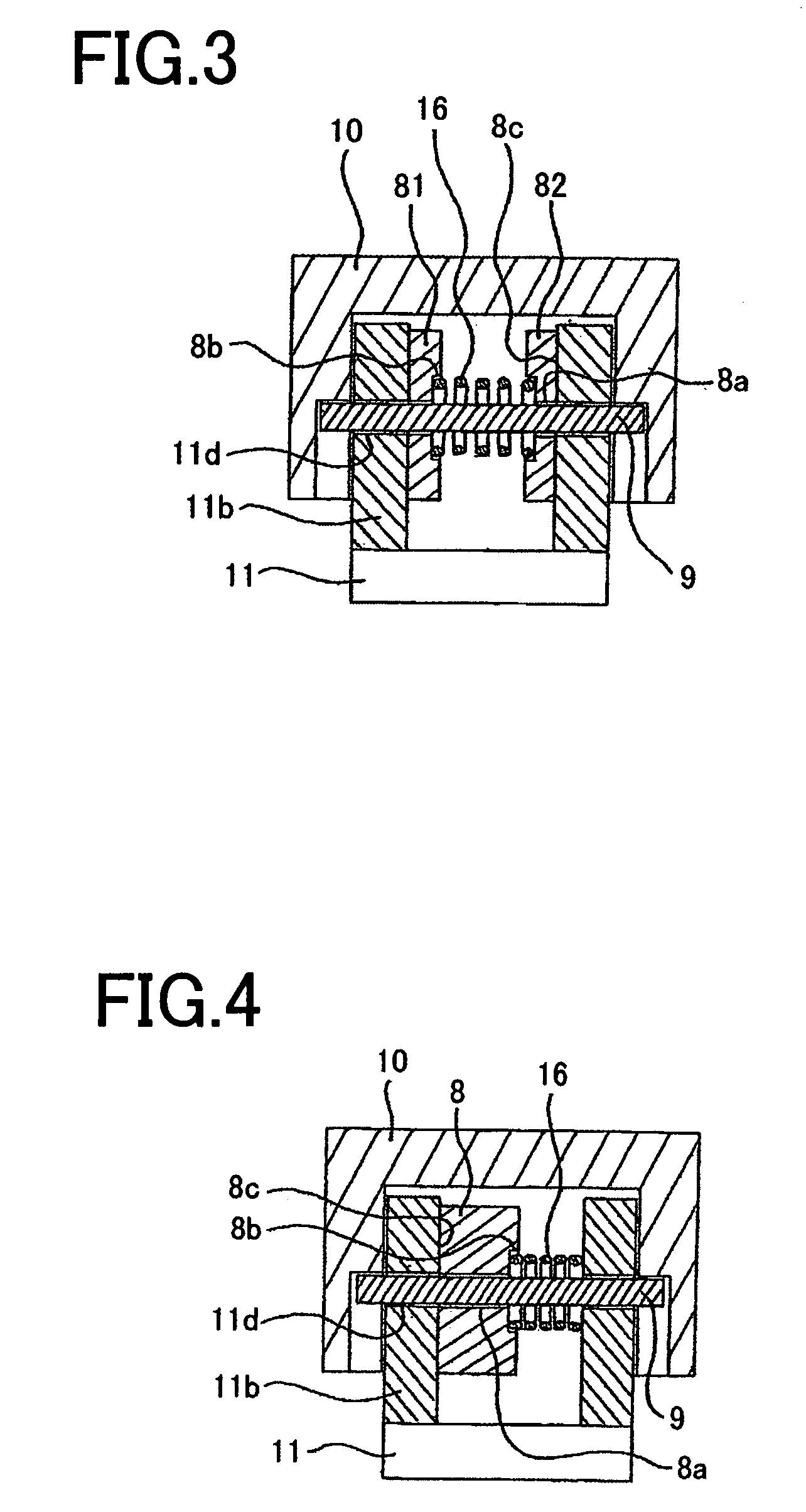
[0038]FIG. 1 is a front elevation illustrating a closed state on of a circuit breaker in Embodiment 1 of the present invention. FIG. 2 is a cross-sectional view taken along Line A-A in FIG. 1, being doubled with a plan of a movable contacting device for single pole. In addition, FIG. 3 is a cross-sectional view taken along Line B-B in FIG. 2.

[0039]Referring to FIG. 1, an enclosure 1 and a case base 2 constitute a case for a circuit breaker 101, each being formed of synthetic resin. The case base 2 houses an opening / closing mechanism 102, an operating handle 3 that is cooperated with the opening / closing mechanism 102 protrudes outwardly from an opening 1a of the enclosure 1, for an operating handle 3, so that the circuit breaker is hand-operable from the outside thereof, as is known in the art. It is also well known in the art that present on the right side of the drawing with respect to the operating handle 3 position of the circuit breaker 101 being in the closed state, is, for ins...

embodiment 2

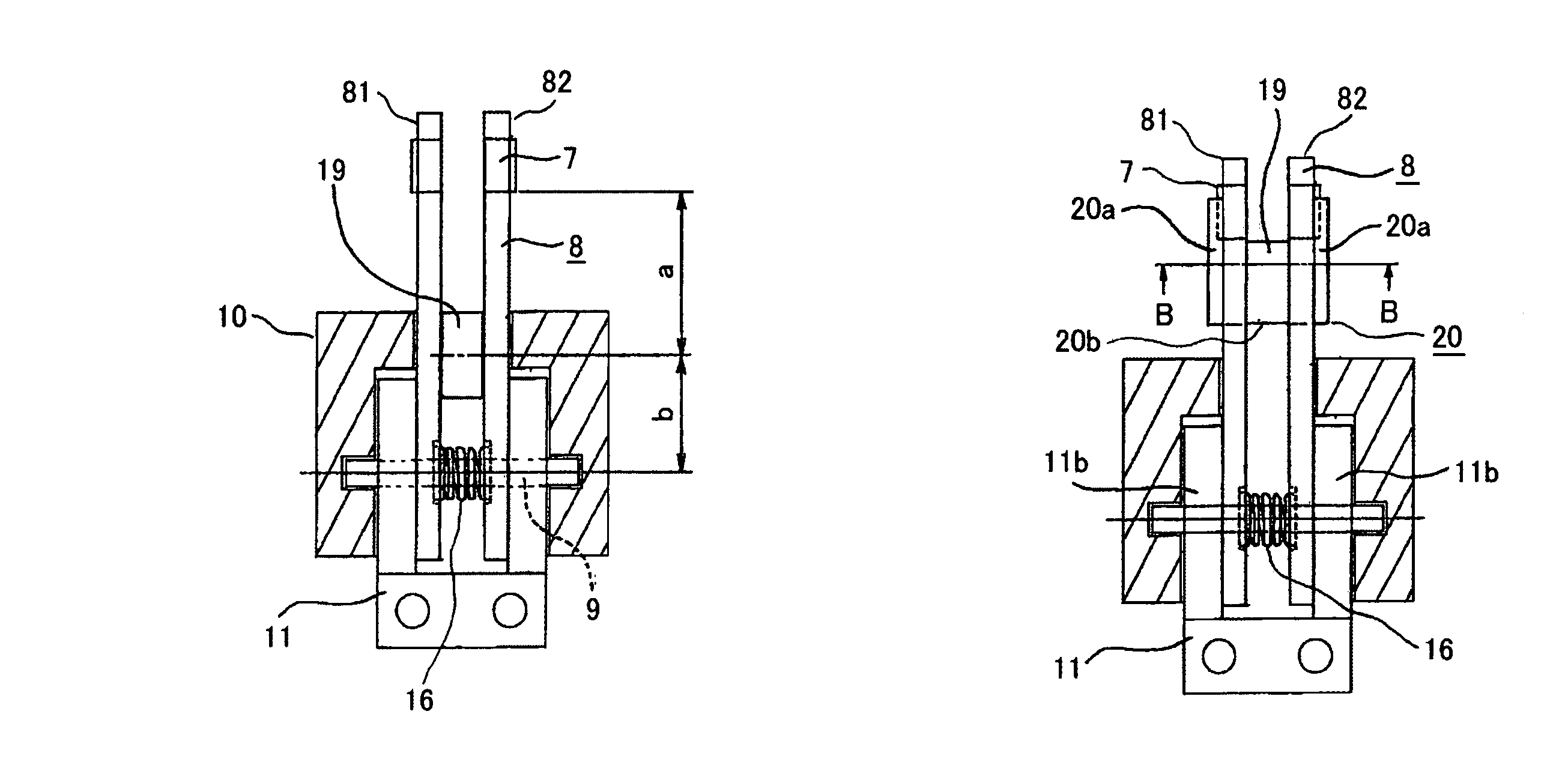
[0044]In Embodiment 1, assuming increase of the current rating based upon increase of the current-carrying capacity, a plurarity (two) of movable contact arm members 81 and 82 has been used. Another case in which increase of current rating is not anticipated, or a thick movable contact arm 8 is used will be described as Embodiment 2. Here, FIG. 4 is a view corresponding to FIG. 3 in Embodiment 2.

[0045]Referring to FIG. 4, recesses 8b are provided on the opposite lateral side of contact areas 8c of the movable contact arm 8. An elastic member 16 loosely mounted on a shaft 9 is inserted into the recesses 8b. As is the case with Embodiment 1, the elastic member 16 is a compression spring, and the movable contact arm 8 is inserted between a pair of connecting conductors 11b so that the elastic member 16 is sandwiched between the movable contact arm 8 and a movable contact arm support 11. Here, fitting a compression spring, not shown, and the shaft 9 is the same as that shown in Embodime...

embodiment 3

[0047]The fact that also in Embodiment 1 an elastic member 16 is not exteriorly disposed, fully contributes to miniaturization of a shuntless current-carrying mechanism. However, in order to generate a certain level of a contact pressure between a movable contact arm 8 and a movable contact arm support 11, the wire diameter and the winding number need to be taken into account, and a spacing between the movable contact arm 8 (Dimension D as shown in FIG. 2) should not be negligible. A case in which Dimension D is made as narrow as possible will be described as Embodiment 3. Here, FIG. 5 and FIG. 6 are views corresponding to FIG. 2 and FIG. 4 in Embodiment 3, respectively, and FIG. 7 is an outline perspective view of a helical spring employed in Embodiment 3.

[0048]Referring to FIG. 5(a), recesses 8b are provided on lateral surfaces, of movable contact arm members 81 and 82 arranged in parallel, facing each other, i.e., on the opposite side of the surfaces that abut on the movable cont...


PUM


Abstract

A movable contacting device in a circuit breaker comprises: a crossbar linked with the opening / closing mechanism and carried so as to pivot cooperatively with the opening / closing mechanism; a movable contact arm engaged, so as to cooperational with the crossbar, with a shaft fitted into a mutually opposing recesses in the crossbar; and a movable contact arm support fixed to the case accomodating the opening / closing mechanism and having mutually opposing through-holes through which the shaft is passed; and the movable contact being configured so that the movable contact slides between surfaces of movable contact arm support having the mutually opposing through-holes; and the construction of a single-pole portion of the movable contact arm is constituted by arranging in parallel two movable contact arm members each having a movable contact at one end, and in a shaft-supporting portion at the other end, an elastic member is sandwiched between the two movable contact arm members. With this arrangement, circuit breakers provided with a movable contacting device that is small in size and stable in contact resistance can be made available.

Description

TECHNICAL FIELD[0001]The present invention relates to circuit breakers such as molded-case circuit breakers and earth-leakage circuit breakers, and more particularly, to stabilization of contact resistance values in a sliding-contact method of a movable contacting device.BACKGROUND ART[0002]The opening / closing lifetime of the circuit breaker includes a mechanical one and an electrical one. The former depends chiefly on wear and damage of its mechanical component. Meanwhile, the latter is dominated by, in addition to those, wear and tear of contacts, normally being shorter in lifetime than the former. Regarding the damage of the mechanical component, a fatigue burnout of parts that perform electrical connections by means of a flat stranded copper wire or a sheet metal that provides flexibility (hereinafter referred to as shunt), is particularly a major cause that limits the opening / closing lifetime.[0003]As a measure for eliminating the cause, a current-carrying mechanism is known th...

Claims


Application Information

Patent Timeline
Patent Type & Authority Patents(United States)
IPC IPC(8): H01H1/00H01H83/00H01H77/00H01H75/00H01H1/22
CPCH01H1/226H01H1/5833H01H73/04H01H71/528
Inventor KAKISAKO, HIROYUKIITO, HITOSHIMAETA, KOZOKAWAMURA, MASANORIKOUMOTO, SHIGEKI
Owner MITSUBISHI ELECTRIC CORP
Why Eureka
Try Eureka