
Durable pallet and pallet block

a technology of durable pallets and pallet blocks, applied in the field of plastic pallets, can solve the problems of wood pallets suffering from splintering, lack of hygiene, and fluctuation of weight, and achieve the effect of reducing damage during impact and improving aesthetic appearan

Active Publication Date: 2010-08-24
CHEP TECH PTY LTD
View PDF37 Cites 49 Cited by
  • Summary
  • Abstract
  • Description
  • Claims
  • Application Information

AI Technical Summary

Benefits of technology

The invention provides a pallet with improved strength and durability. The pallet includes a plurality of pallet blocks that are joined together, including pallet blocks at corners, along the perimeter, and at the center. The pallet blocks have rounded corners to reduce damage during impact. The top deck includes pallet blocks with inner sleeves and radial ribs that increase the strength of the pallet blocks. The bottom deck includes pallet blocks with outer sleeves and bosses or posts. The pallet blocks are arranged to provide four-way symmetry. The top deck also includes pallet blocks that project upwardly and the bottom deck includes pallet blocks that project downwardly. The pallet blocks are joined together using a heat staking process or other fastening mechanisms. The invention provides advantages over prior systems and is suitable for various applications.

Problems solved by technology

For example, wood pallets suffer from problems including splintering, weight fluctuations due to varying moisture content, and / or lack of hygiene due to mold and / or fungi that result from the moisture, among other problems.
Metal pallets suffer from problems including high cost of manufacture, corrosion and / or bending, among other problems.

Method used


Image

  • Durable pallet and pallet block
  • Durable pallet and pallet block
  • Durable pallet and pallet block

Examples


Embodiment Construction

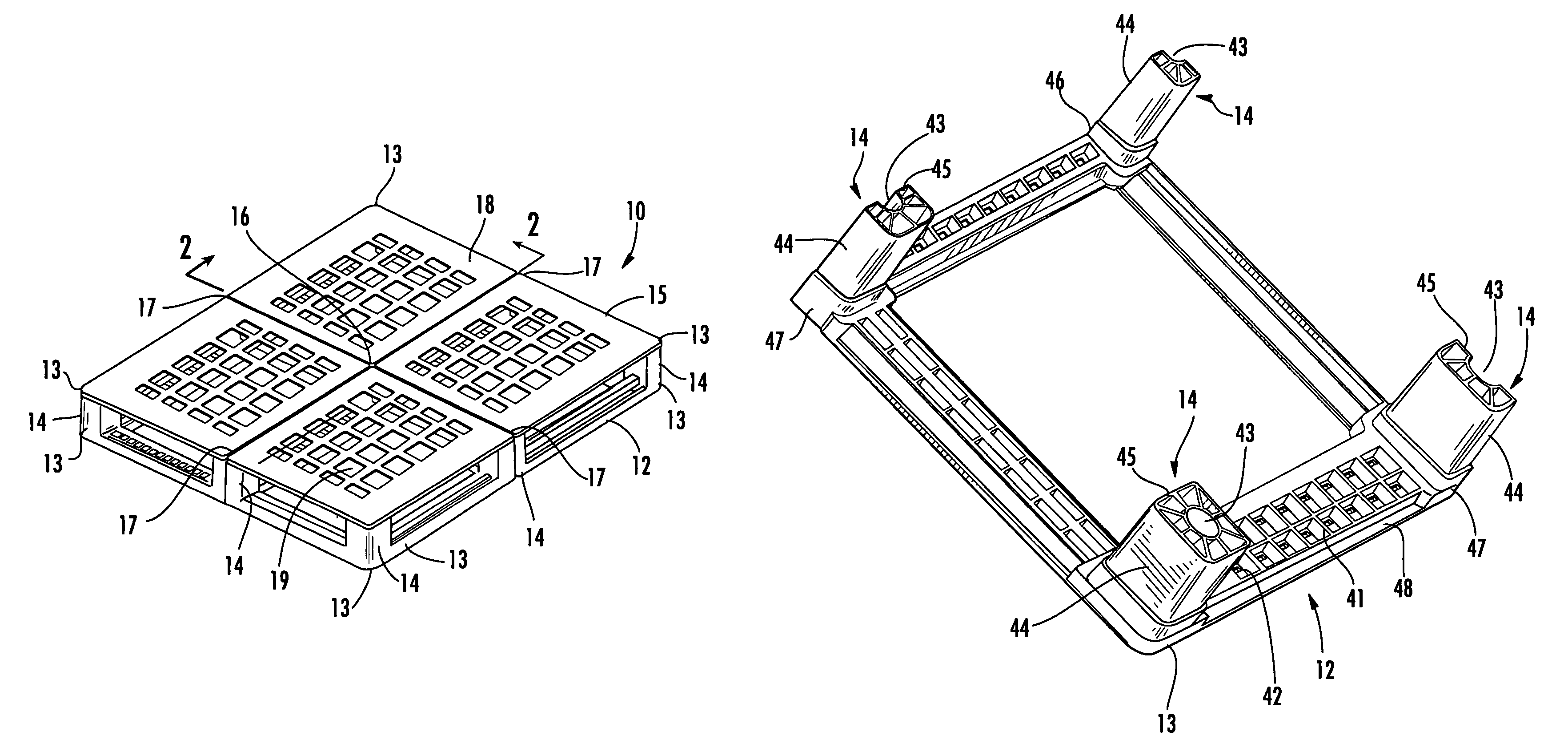
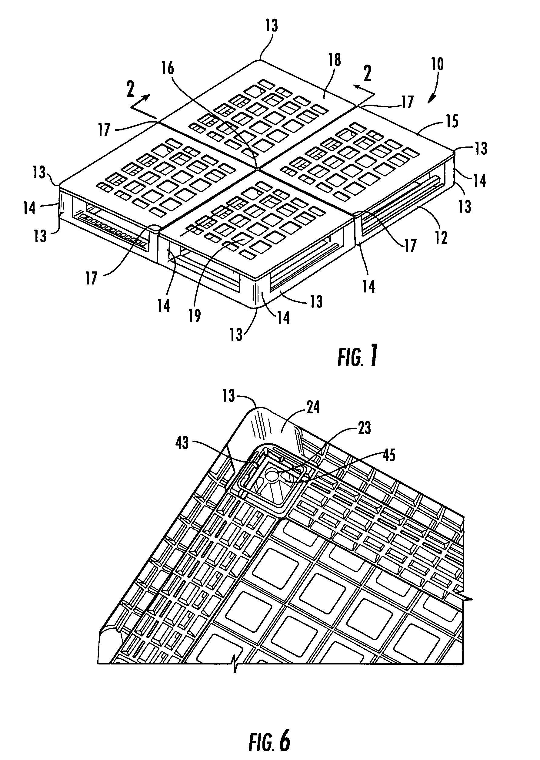
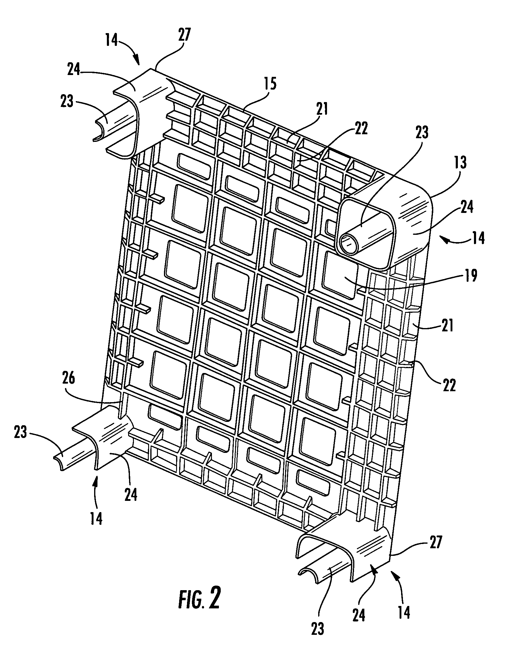
[0022]FIG. 1 illustrates a pallet 10 according to one embodiment of the invention, having two sections that are joined together. According to one embodiment, pallet 10 may include a lower section, or bottom deck 12, and an upper section, or top deck 15 that are separately molded. Top deck 15 may include a generally flat, planar surface 18 having a plurality of holes 19, wherein holes 19 provide several benefits including reduced surface area of top deck 15, increased breathability for materials placed on top deck 15, reduced weight of top deck 15 and / or other benefits. According to one embodiment of the invention, an outer 100 mm perimeter of planar surface 18 may contain no holes. Bottom deck 12 may include a perimeter shape that substantially matches the perimeter shape of top deck 15. Bottom deck 12 may include a rectangular perimeter shape having cross members that intersect a center portion of each side of the rectangular perimeter, midway between corners 13.

[0023]According to ...


PUM


Abstract

A pallet includes an upper deck, and first joining members that project downwardly from the upper deck. Each first joining member includes an outer sleeve and a post positioned therein. The pallet includes a lower deck, and second joining members that project upwardly from the lower deck. Each second joining member includes an inner sleeve and a post receiving cavity positioned therein. The first and second joining members are coupled together to define pallet blocks joining the upper and lower decks. Each inner sleeve and post receiving cavity of the second joining members receives a corresponding post and outer sleeve of the first joining members.

Description

FIELD OF THE INVENTION[0001]The invention relates to plastic pallets that are used to support goods and other articles. More particularly, the invention relates to multi-piece plastic pallets that are configured to receive a lifting device.BACKGROUND OF THE INVENTION[0002]Pallets are flat transport structures that are made of wood, plastic and / or metal. Pallets are used to stably support a variety of goods that are placed on a top surface of the pallet. Pallets enable goods to be stored and / or transported using lifting devices, such as forklifts or other jacking devices.[0003]Wood and metal pallets have many drawbacks. For example, wood pallets suffer from problems including splintering, weight fluctuations due to varying moisture content, and / or lack of hygiene due to mold and / or fungi that result from the moisture, among other problems. Metal pallets suffer from problems including high cost of manufacture, corrosion and / or bending, among other problems. While plastic pallets offer...

Claims


Application Information

Patent Timeline
Patent Type & Authority Patents(United States)
IPC IPC(8): B65D19/38
CPCB65D19/0095B65D19/0073B65D2519/00034B65D2519/00069B65D2519/00273B65D2519/00293B65D2519/00308B65D2519/00323B65D2519/00333B65D2519/00407B65D2519/00412B65D2519/00562B65D2519/00567B65D2519/00104B65D2519/00378B65D2519/00756Y10S108/901
Inventor NAIDU, VISHNUBEERENSSON, JAMES
Owner CHEP TECH PTY LTD
Learn More