Electric tankless water heater

a technology of electric tank and water heater, which is applied in the direction of fluid heater, lighting and heating apparatus, immersion heating arrangements, etc., can solve the problems of inherently energy inefficient, temperature spikes in output water, and occurrence of temperature spikes upon change of hot water demand, so as to facilitate maintaining the liquid outlet temperatur

Active Publication Date: 2010-08-24
RHEEM MFG CO
View PDF41 Cites 29 Cited by
  • Summary
  • Abstract
  • Description
  • Claims
  • Application Information

AI Technical Summary

Benefits of technology

[0011]In the various aspects of the invention, the liquid heaters comprise one or more electrical resistance heating elements for heating the liquid. Preferably, the electrical resistance heating elements are continuous, sheathless, coils having a mechanically stressed portion that bridges a liquid inlet channel and a liquid outlet channel of a liquid heater and an electrically conductive member configured to substantially eliminate current flow through the mechanically stressed portion.
[0018]In preferred aspects, the tankless liquid heater of the present invention includes a controller, which provides thermostatic control, for example, by monitoring one or more of liquid outlet temperature, inlet flow rate, and outlet flow rate; and adjusting the energization of liquid heaters and the current flow to one or more electrical resistance heating elements. In various embodiments, the controller adjusts the energization of liquid heaters and the current flow to one or more electrical resistance heating elements to facilitate maintaining liquid outlet temperature below a maximum temperature value. In various embodiments, the maximum temperature value is in the range between about 102° F. to about 106° F., and preferably the maximum temperature value is about 105° F.

Problems solved by technology

Although such heated tank systems can provide hot water at a relatively high flow rate, they are inherently energy inefficient because the water in the tank is continually reheated even when water is not being used on a regular basis.
However, one common draw back of traditional tankless water heater systems is the occurrence of temperature spikes upon changes in hot water demand.
In contrast, in a typical tankless hot water heater system, when hot water-demand increases the system must increase the energy output of its heating elements to respond to the increased demand (and concomitant increased input water flow rate).
Temperature spikes in the output water can then occur when there is a sudden decrease in hot water demand because of the delay in adjusting the energy output of the heating elements for the reduction in input water flow rate.
Such temperature spikes in the flow from water fixtures for human use (e.g., sinks, showers, etc.), besides being unpleasant, can cause a person to reflexively jerk their hand away from the water stream, which can pose risks to equipment or others if the person happens to be washing a fragile or sharp piece of equipment at the time.
Temperature spikes can be particularly troublesome for fixtures with automatic faucets (e.g., touch-free faucets) because of the very rapid shut-off characteristic (typically about 50 milliseconds) of the solenoid valves used in such faucets.

Method used


Image

  • Electric tankless water heater
  • Electric tankless water heater
  • Electric tankless water heater

Examples


example 1

Examples of Temperature Spikes Using Traditional Heater Systems

[0062]In this example, measurements of output water temperature for various changes in input water flow rates were performed on two commercially available electric tankless water heaters (Heater A and Heater B) connected to a Bradley three-station sink (Bradley Corp., Menomonee Falls, Wis.). The faucets of the Bradley three-station sink were each controlled by a solenoid valve with a rated shutting time of 50 milliseconds.

[0063]The data of FIGS. 7A and 7B was recorded using a Monarch Data Chart 4600 data acquisition recorder (Monarch Instruments, Amherst, N.H.). FIG. 7A depicts the measurements for Heater A. Heater A was an Eemax™ EX110TC model heater (available from Eemax, Inc., Oxford, Conn.). FIG. 7B depicts the measurements for Heater B. Heater B was a Chronomite™ E-90RL model heater (available from Chronomite Laboratories, Inc., Harbor City, Calif.).

[0064]Measurement of the input water flow rate was made using a rot...

example 2

Temperature Variation Using an Embodiment of the Invention

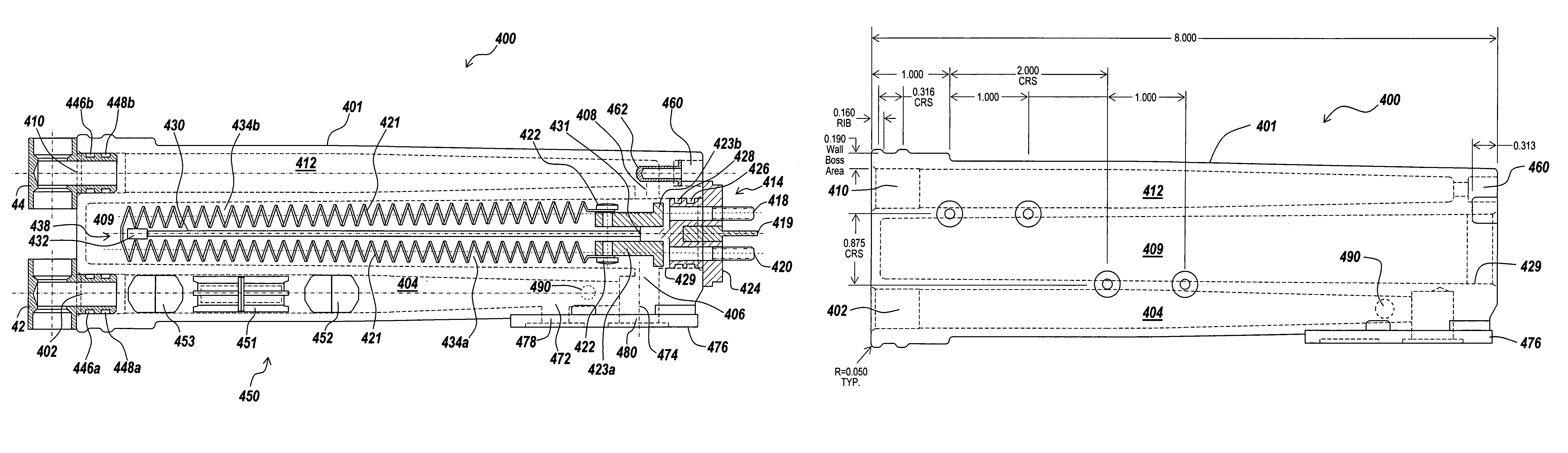
[0072]In this example, measurements of output water temperature for various changes in measured input water flow rates were performed on an embodiment of an electric tankless water heater system of the invention (“the test water heater system”) connected to the same Bradley three-station sink of Example 1. As in Example 1, the faucets of the Bradley three-station sink were each controlled by a solenoid valve with a rated shutting time of 50 milliseconds. As in Example 1, the data of FIGS. 8 and 9 was recorded using a Monarch Data Chart 4600 data acquisition recorder (Monarch Instruments, Amherst, N.H.). The test water heater system of Example 2 was substantially similar to that described in the context of FIGS. 1-6. The controller of the test water heater system was set to maintain the output water temperature at about 105° F.

[0073]FIG. 8 depicts measurements of output water temperature for various changes in measured input w...


PUM


Abstract

In various aspects, the present invention provides an electric tankless liquid heater system capable of delivering liquid, such as, for example, water, with an acceptable increase in output liquid temperature upon a sudden and substantial decrease in liquid demand. In various aspects, the electric tankless liquid heater comprises an inlet manifold and a plurality of liquid heaters the inlets of which are connected in a parallel flow relationship by the inlet manifold, and the outlets of which are each connected to a separate outlet conduit, and which is configured to provide water to a plurality of automatic water fixtures with a less than about 2° F. (about 1.1° C.) increase in output water temperature upon about a one-and-a-half-fold or greater decrease in water demand that occurs in less than about 500 milliseconds as measured by the increase time of the inlet liquid pressure.

Description

BACKGROUND[0001]The most common approach for providing hot water in both domestic and commercial settings involves the use of large tanks for the storage of hot water. Although such heated tank systems can provide hot water at a relatively high flow rate, they are inherently energy inefficient because the water in the tank is continually reheated even when water is not being used on a regular basis.[0002]Another approach to providing hot water involves the use of a tankless water heater system that heats water only when hot water is being used. Such tankless water heater systems, also referred to as demand water heater systems, can often provide a more energy efficient means of heating water than storage systems using the same type of heating (e.g., gas, electric, etc.). However, one common draw back of traditional tankless water heater systems is the occurrence of temperature spikes upon changes in hot water demand. Traditional reservoir type hot water heaters typically do not expe...

Claims


Application Information

Patent Timeline
Patent Type & Authority Patents(United States)
IPC IPC(8): F22B27/00
CPCF24H1/102F24H9/2028F24H15/238F24H15/175F24H15/219F24H15/37F24H15/31F24H15/407
Inventor FABRIZIO, EDWARD VINCENT
Owner RHEEM MFG CO
Why Eureka
Try Eureka