
Heat transfer tube assembly with serpentine circuits

a technology of heat transfer tube and serpentine circuit, which is applied in the direction of heating apparatus, defrosting, heating apparatus, etc., can solve the problems of reducing thermal performance, increasing cost, lowering pressure drop, etc., and achieves low pressure drop, high thermal performance, and efficient heat transfer

Active Publication Date: 2010-08-24
BALTIMORE AIRCOIL CO INC
View PDF22 Cites 38 Cited by
  • Summary
  • Abstract
  • Description
  • Claims
  • Application Information

AI Technical Summary

Benefits of technology

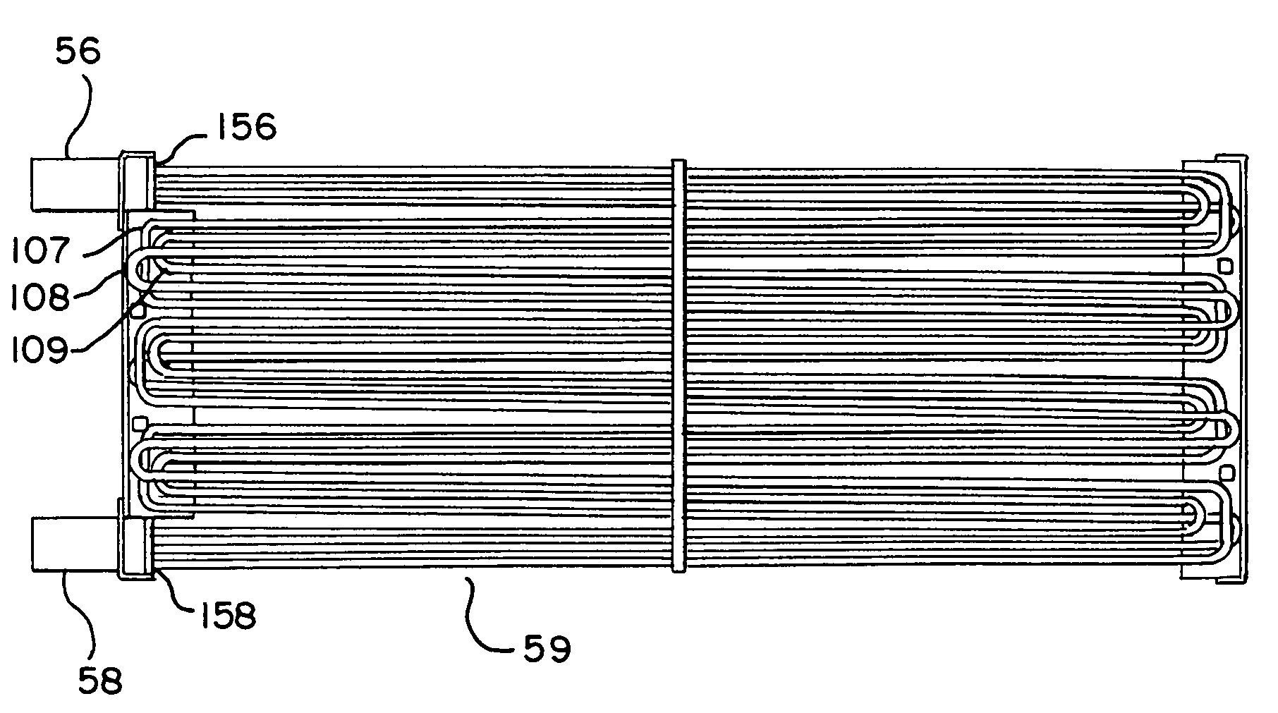
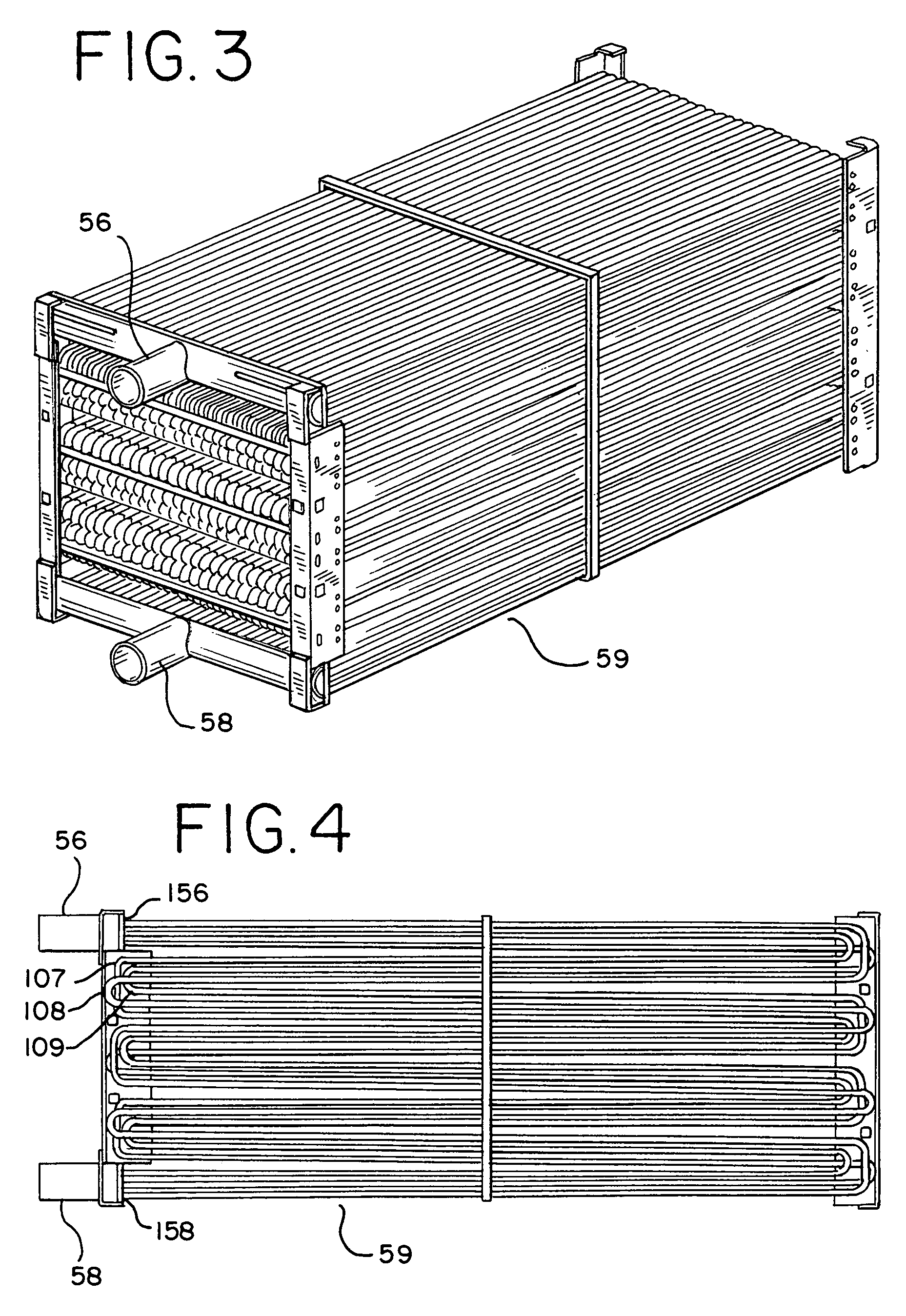
The invention is a heat transfer tube assembly with a triple circuited serpentine coil circuit that overcomes the drawbacks of prior art cooling systems. The design has a compact arrangement with a uniform flow of air and spray water throughout the assembly. The triple circuit coil can be fed from either the top or bottom header, but most often is fed from the bottom header as it has the most benefit in units of combined coil / fill design. The design results in an efficient heat transfer with a low pressure drop and a high thermal performance.

Problems solved by technology

To solve the pressure drop dilemma, so-called “QUAD” serpentine bundles were developed, where groupings of four rows of circuits are fed from a common header, significantly lowering pressure drop, but simultaneously lowering thermal performance and increasing cost.
In the designs for QUAD serpentine bundles, thermal performance is reduced due to the lower tube velocity, which results in a lower internal film heat transfer coefficient.
In addition, fewer passes of the fluid to be cooled through the spray water chambers reduces the potential heat transfer.
Performance is also negatively impacted as the heated spray water from one circuit falls onto a lower circuit below that is fed with the same temperature fluid.
Additionally, multiple connections would often be required to accommodate the coil flow on the standard serpentine, leading to increased coil cost and installed cost for higher flow applications.
The prior art described above suffers various deficiencies in its application to closed circuit cooling towers.

Method used


Image

  • Heat transfer tube assembly with serpentine circuits
  • Heat transfer tube assembly with serpentine circuits
  • Heat transfer tube assembly with serpentine circuits

Examples


Embodiment Construction

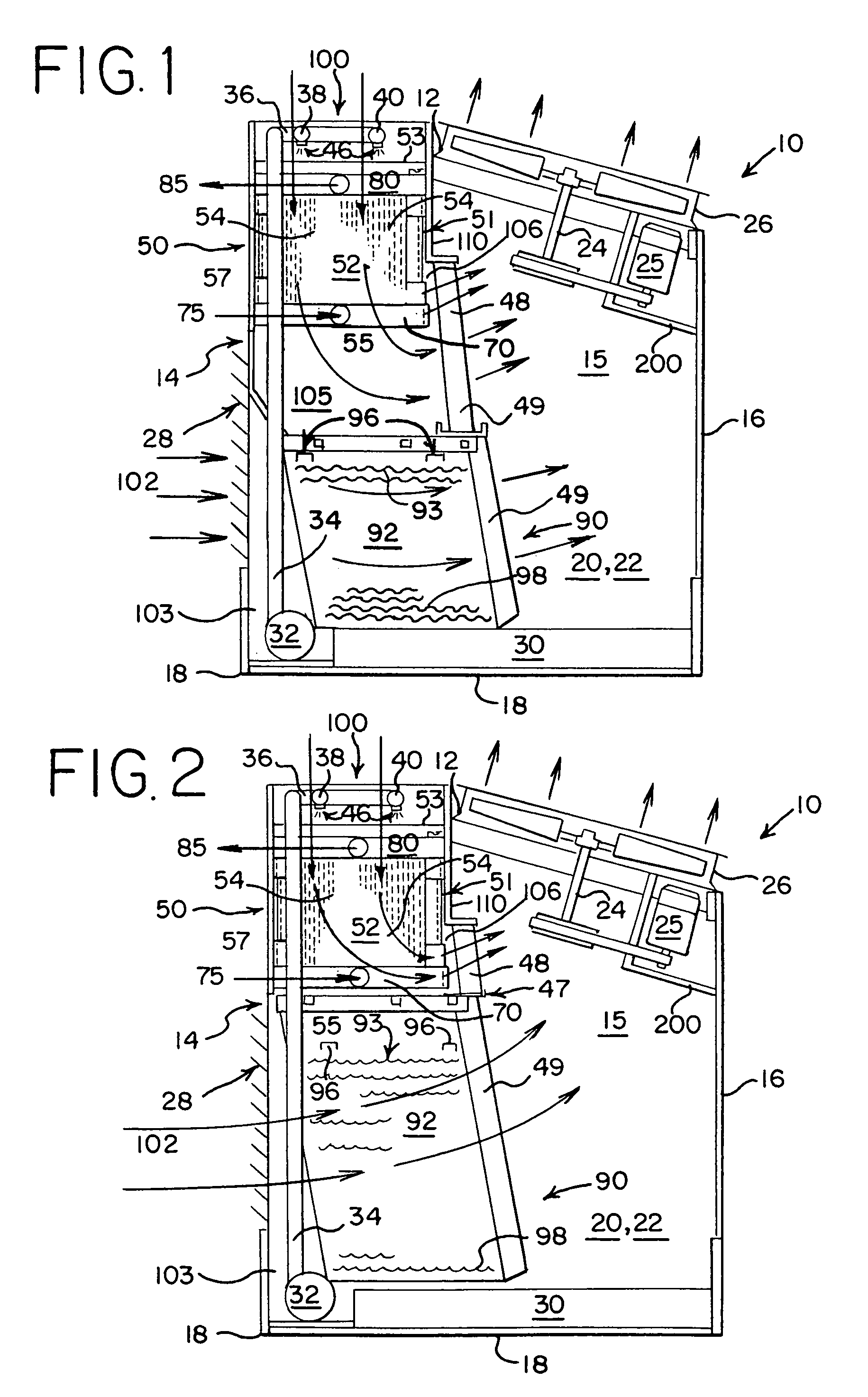
[0013]The present invention provides reconfiguration of the coil assemblies in closed-circuit cooling towers illustrated in FIG. 1, and more particularly coil circuits for units operating at high internal fluid flows. In this context, fluids refer to gasses and liquids but are typically liquid. The physical environment and typical position of the coil assemblies are illustrated in FIG. 1. Closed-circuit cooling tower 10 of FIG. 1 is illustrative of a combined coil fill structure, but is an exemplary illustration and not a limitation to the present invention.

[0014]Referring now to FIG. 1 of the drawings, the heat exchange apparatus 10 in accordance with the invention is shown and is well known in the art as a closed-circuit cooling tower. Generally, apparatus 10 includes an enclosure structure which contains a multi-circuit indirect evaporative fluid cooling section 50, a direct evaporative heat exchange section 90, a lowermost evaporative liquid collection sump 30, and an uppermost ...


PUM


Abstract

A method and apparatus are provided for cooling fluids entering a closed circuit cooling tower. A triple circuit assembly is used to cool the fluid in the closed loop. The triple circuit assembly design allows a heat transfer tube bundle to maintain a relatively low pressure drop, but without simultaneously lowering thermal performance to a significant degree as compared to traditional double serpentine or QUAD serpentine designs.

Description

BACKGROUND OF THE INVENTION[0001]This invention relates to an apparatus and method for an evaporative fluid cooler as a closed circuit cooling tower or as an evaporative condenser, in which an alternative coil circuiting arrangement is used to cool a the fluid or condense a gas in the closed loop.[0002]The prior art includes the use of closed loop cooling towers for applications relating to industrial process cooling. Open circuit cooling towers have been used for large chilled water systems for many years. More recently, closed circuit cooling towers have been used for condenser water cooling systems for packaged chillers. Closed circuit cooling towers are also used on systems with many small, hard to clean heat exchangers, such as water source heat pumps and welding machines.[0003]In a typical coil tube arrangement for a closed circuit cooling tower, circuits are provided between an upper header with a fluid inlet nozzle and a lower header with a fluid outlet nozzle. The individua...

Claims


Application Information

Patent Timeline
Patent Type & Authority Patents(United States)
IPC IPC(8): F28D1/00F28F9/02F28F1/10F28D7/06F28D7/02F28F1/00
CPCF28C1/14F28D1/0477F28D5/02F28F9/02Y02B30/70
Inventor MORRISON, FRANK T.CARTER, THOMAS P.
Owner BALTIMORE AIRCOIL CO INC
Learn More