Printhead with heaters offset from nozzles

a technology of printheads and heater elements, which is applied in printing and other directions, can solve the problems of thermal inkjet printheads that are traditionally prone to overheating, build up heat in the printhead, and ink will boil in an uncontrolled manner, and achieve the effect of resisting flow out of fluidic drag

Active Publication Date: 2010-08-24
MEMJET TECH LTD +1
View PDF5 Cites 8 Cited by
  • Summary
  • Abstract
  • Description
  • Claims
  • Application Information

AI Technical Summary

Benefits of technology

[0013]The vapor bubble generated by the heater can be asymmetrical because of the configuration of the heater relative to the nozzle and the ink inlet. As the bubble grows, it not only forces ink from the nozzle but also creates a small back flow of ink through the ink inlet. The back flow is usually negligible compared to the ink ejected because the fluidic drag resisting flow out of the inlet compared to flow out of the nozzle is very high. If the ink inlet is at the side of the chamber (that is, the inlet flow is parallel to the plane of the heater and the nozzle), the small back flow of ink allows the bubble to skew towards the ink inlet. The pressure pulse through the ink is likewise skewed and meets one side of the ejection aperture slightly before the other side.
[0014]The ink drop ejected through the nozzle will trail a thin stem of ink behind it immediately after ejection. Eventually the momentum of the drop overcomes the surface tension in the trailing stem of ink to break the stem so that the drop completely separates from the printhead. With a skewed pressure pulse ejecting the drop, the trailing stem of ink pins to one particular side or part of the ejection aperture. Before the thin stem of ink between the nozzle and the ejected drop breaks, the surface tension in the stem can drag the droplet away from a trajectory normal to the plane of the nozzles. This causes consistent droplet misdirection. However, the invention addresses this by offsetting the heater and nozzle from each other so that the pressure pulse is much less skewed when it is incident on the nozzle aperture.

Problems solved by technology

Thermal inkjet printheads are traditionally prone to overheating.
The rapid successive vaporization of ink during printing can build up heat in the printhead.
If too much builds up in the printhead, the ink will boil in an uncontrolled manner.
The overheating problem has limited the firing frequency of the nozzles and printhead size, both of which reduce the print speed.
Unfortunately drop volumes this small are susceptible to trajectory misdirection.
It will be appreciated that any misdirection of the ejected ink drops is detrimental to print quality.
Fluidic symmetry around the heater is not possible unless the heater is suspended directly over the ink inlet.

Method used


Image

  • Printhead with heaters offset from nozzles
  • Printhead with heaters offset from nozzles
  • Printhead with heaters offset from nozzles

Examples


Embodiment Construction

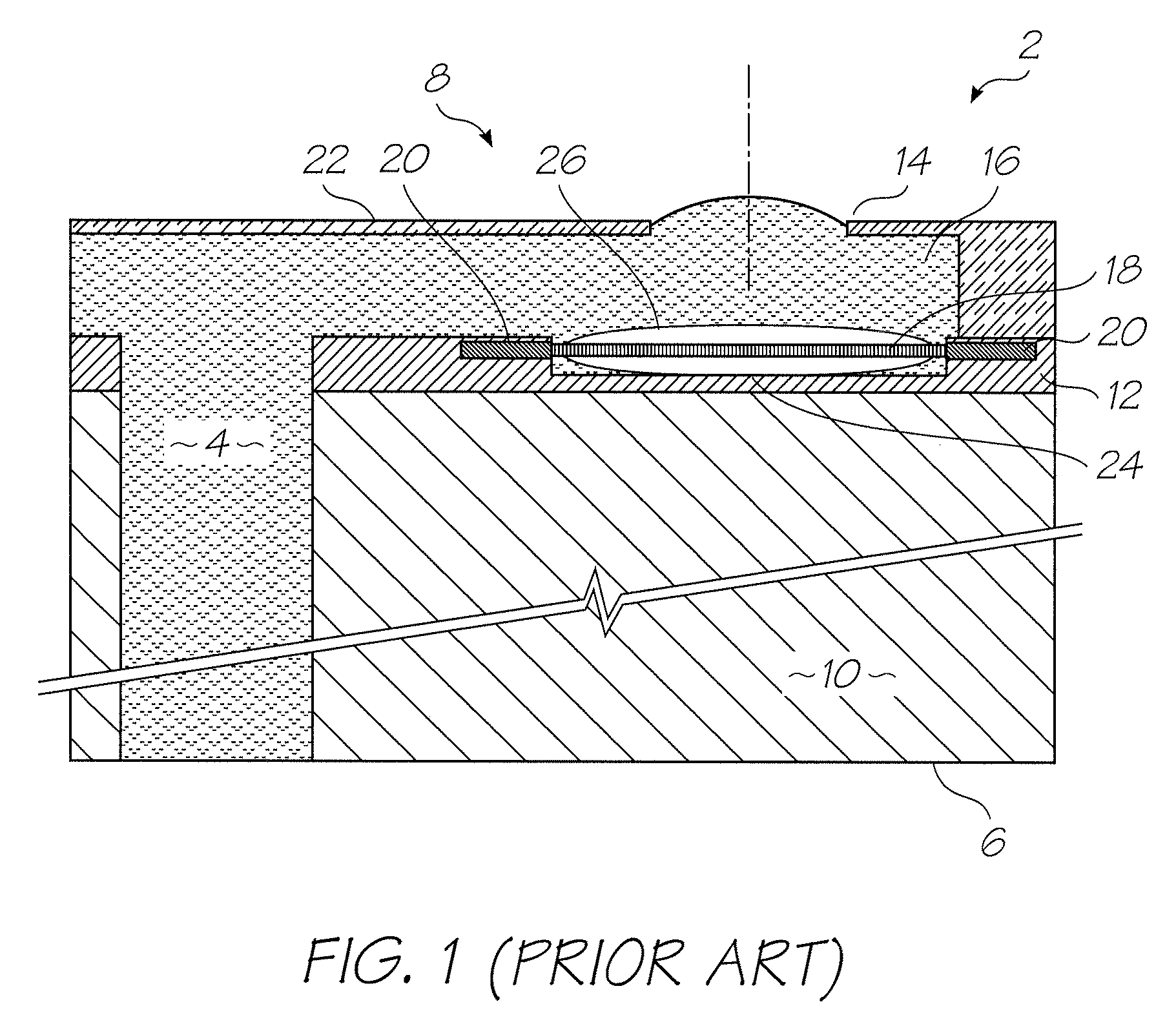
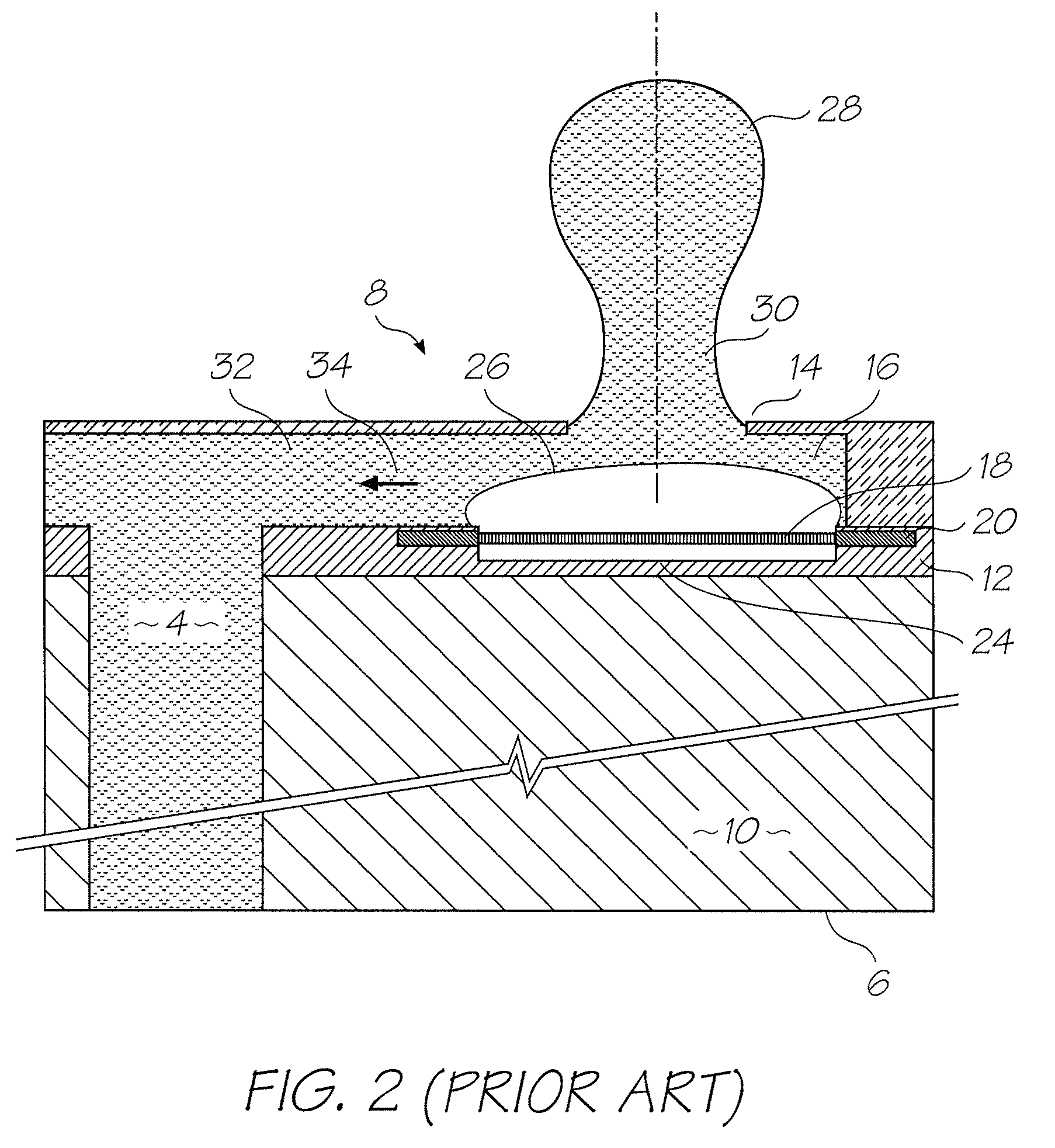
[0027]FIGS. 1 to 5 sketch the ejection stages of a misdirected drop of ink from a prior art printhead. The printhead structure is a simplified representation of the printheads described in detail in U.S. Ser. No. 11 / 246,687 filed Oct. 11, 2005, the contents of which are incorporated herein by reference. While the invention is described here with reference to this particular printhead design, it will be appreciated that this is purely illustrative and in no way restrictive on the printheads to which the invention can be applied.

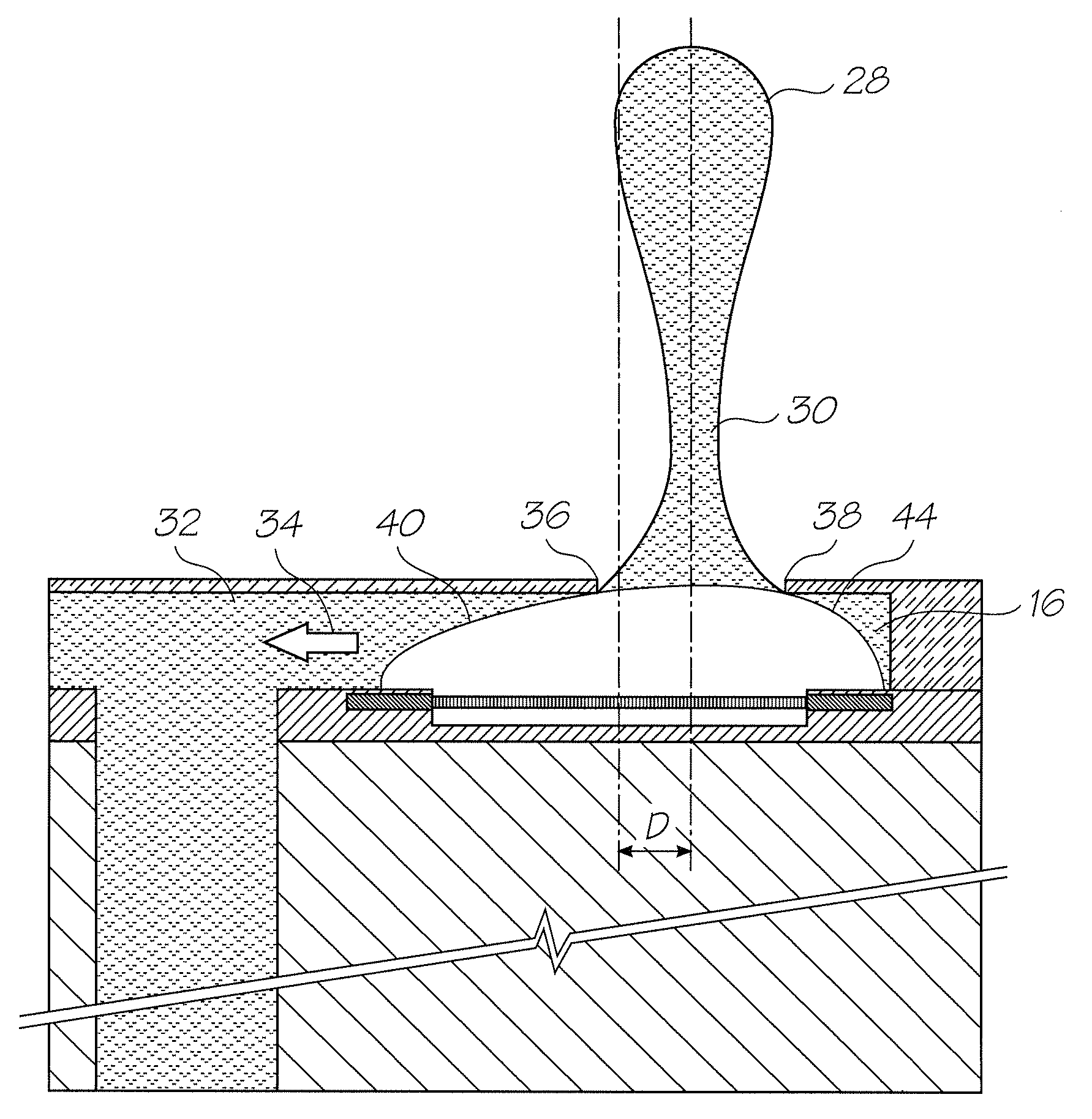
[0028]Referring to FIG. 1, a unit cell of an inkjet printhead 2 is shown. The unit cell is the smallest repeatable unit making up the printhead—in this case the ink supply channel 4 extending from the supply side 6 of the wafer substrate 10, to the ejection side 8 of the wafer substrate, the nozzle 14, the chamber 16, the suspended beam heater 18 with its contacts 20 and associated CMOS drive circuitry 12.

[0029]The heater 18 is a thin rectangular strip suspend...


PUM


Abstract

A thermal inkjet printhead of the roof shooter type that slightly offsets the nozzle aperture centroid from the heater element centroid to correct drop trajectory misdirection caused by vapor bubble asymmetries.

Description

FIELD OF THE INVENTION[0001]The present invention relates to the field of inkjet printers. In particular, the invention concerns printheads with heater elements that vaporize ink to eject an ink droplet from the nozzle.CROSS REFERENCE TO RELATED APPLICATIONS[0002]The following patents or patent applications filed by the applicant or assignee of the present invention are hereby incorporated by cross-reference.[0003]6,405,0556,628,4307,136,18610 / 920,3727,145,6897,130,0757,081,9747,177,0557,209,2577,161,7157,154,6327,158,2587,148,9937,075,68411 / 635,52611 / 65054511 / 65324111 / 653,24011758,64810 / 503,9247,108,4376,915,1406,999,2067,136,1987,092,13009 / 517,5396,566,8586,331,9466,246,9706,442,52509 / 51738409 / 505,9516,374,35409 / 517,6086,816,9686,757,8326,334,1906,745,33109 / 517,54110 / 203,5597,197,6427,093,13910 / 636,26310 / 636,28310 / 866,6087,210,03810 / 902,83310 / 940,65310 / 942,85811 / 706,32911757,38511758,6427,170,6526,967,7506,995,8767,099,05111 / 107,94271937,3411 / 209,71111 / 599,3367,095,5336,914,6867,1...

Claims


Application Information

Patent Timeline
Patent Type & Authority Patents(United States)
IPC IPC(8): B41J2/05
CPCB41J2/1404B41J2/14112B41J2/14032B41J2002/14169B41J2002/14185B41J2002/14475
Inventor NORTH, ANGUS JOHNSILVERBROOK, KIABROWN, BRIAN ROBERTMYERS, SAMUEL JAMESFISHBURN, JENNIFER MIAMALLINSON, SAMUEL GEORGEREICHL, PAUL JUSTIN
Owner MEMJET TECH LTD
Why Eureka
Try Eureka