
Traveling apparatus and method of controlling the same

a technology of traveling apparatus and a control method, which is applied in the direction of electric energy management, electric devices, unicycles, etc., can solve the problems of affecting the driving performance of the vehicle, the rider being in a difficult condition to keep the balance, and the inability to maintain the balance of the rider,

Active Publication Date: 2010-08-24
TOYOTA JIDOSHA KK
View PDF19 Cites 67 Cited by
  • Summary
  • Abstract
  • Description
  • Claims
  • Application Information

AI Technical Summary

Benefits of technology

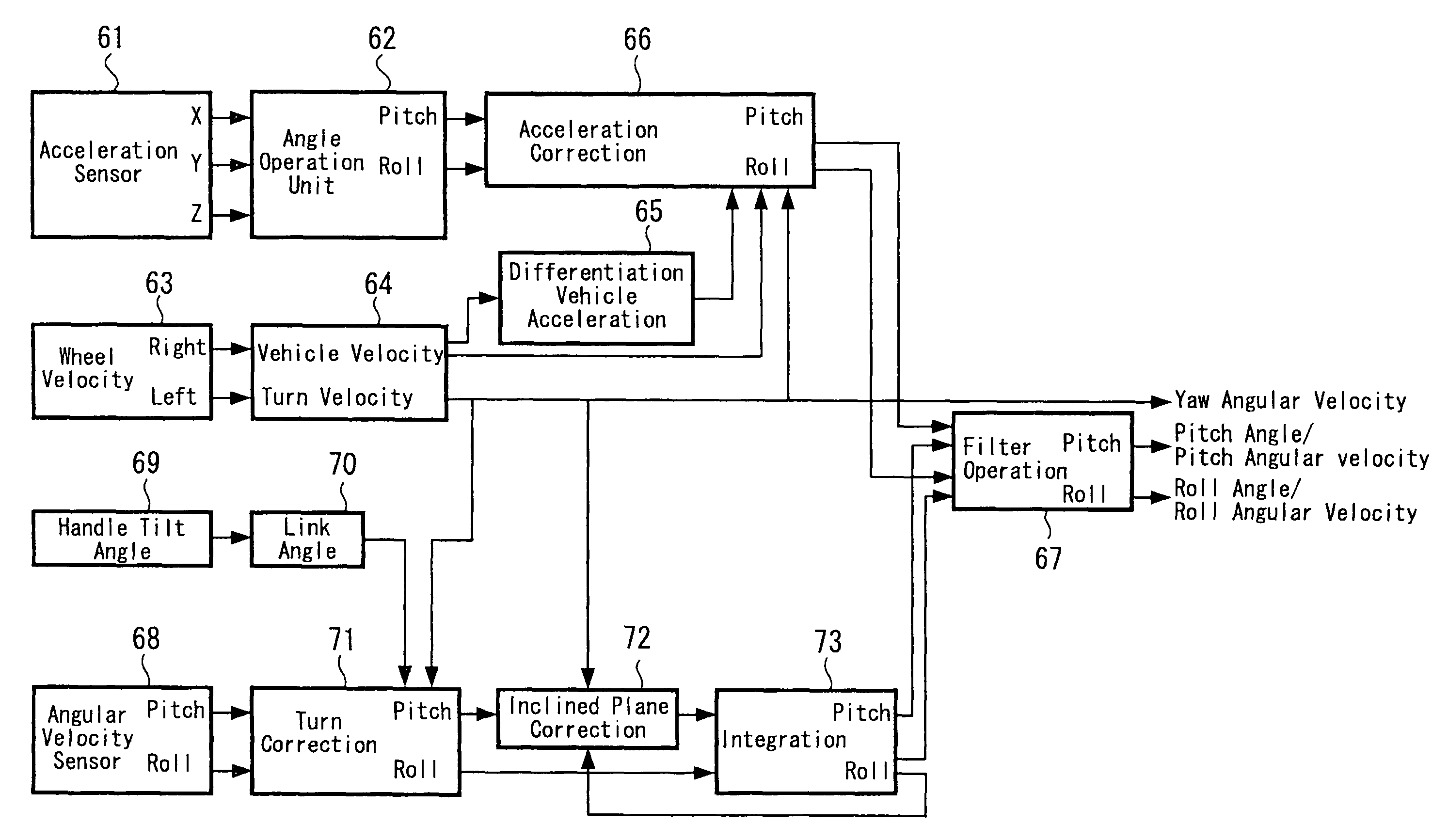
The present invention provides a traveling apparatus that can be controlled to be stable during turns on an inclined plane. By measuring the tilt of the vehicle body in a roll axis direction and canceling out the yaw rate mixed in the pitch angular velocity sensor, an accurate pitch angle can be calculated and used to control the vehicle's stability. This allows for smoother driving performance and reduces the need for measures such as a prohibition on turns on certain inclined planes.

Problems solved by technology

A traveling apparatus traveling with two wheels disposed parallel such as the vehicle described in U.S. Pat. No. 6,288,505 is basically unstable with respect to an anteroposterior direction.
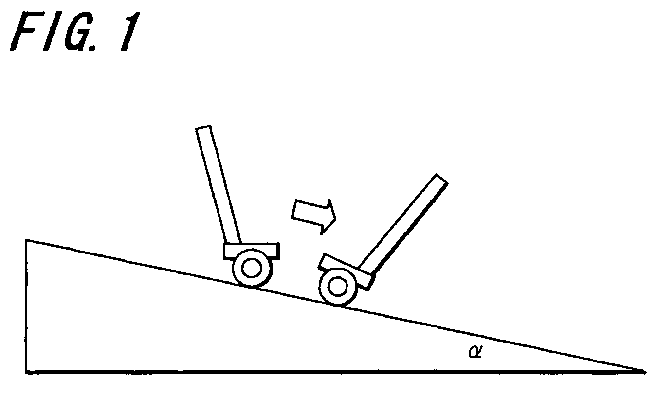
As shown in FIG. 1, since the angle for keeping the balance changes depending on whether the vehicle faces in the ascending direction or in the descending direction of the inclined plane during the turn, there is a possibility of a rider being in a difficult condition to keep the balance.
Hence, measures not allowing a turn on such inclined plane may be needed in a control system of related art, which discourages sufficient driving performance of the vehicle.
It is desirable to control a vehicle for stable traveling, because in related art it may be difficult for a rider to keep the balance of the vehicle since the angle for keeping the balance changes depending on whether the vehicle faces in the ascending direction or in the descending direction of the inclined plane when making the turn on an inclined plane.
Further, measures not to allow a turn on such inclined plane may be required in the control system in related art.

Method used


Image

  • Traveling apparatus and method of controlling the same
  • Traveling apparatus and method of controlling the same
  • Traveling apparatus and method of controlling the same

Examples


Embodiment Construction

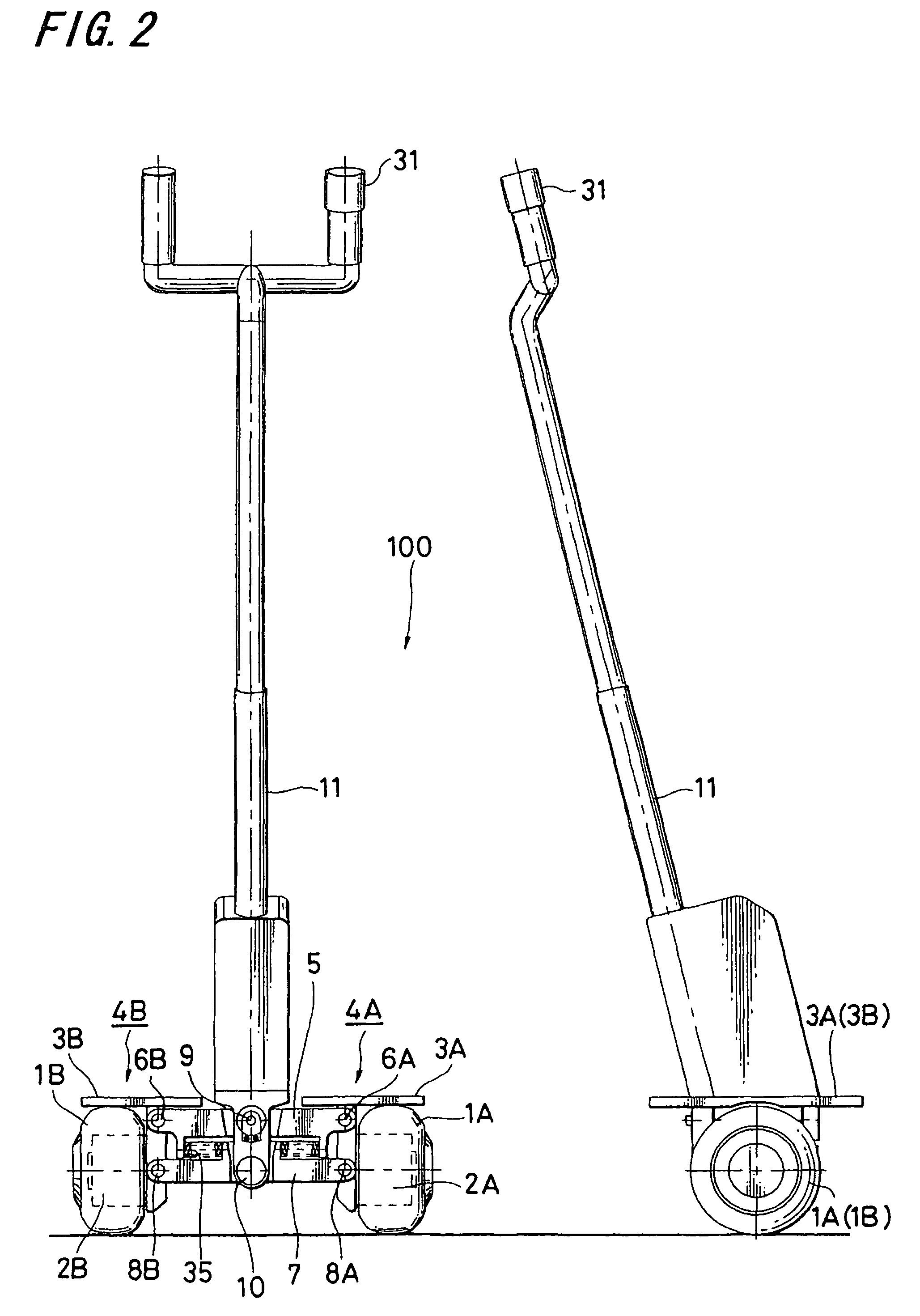
[0032]First, a novel coaxial two-wheel vehicle previously proposed by the applicants of the present invention (Japanese Patent Application No. 2005-117365), to which embodiments of the present invention are applied, is explained by referring to FIGS. 2 and 3. However, embodiments are not limited to the previously proposed coaxial two-wheel vehicle.

[Schematic Configuration of Traveling Apparatus]

[0033]FIG. 2 shows a front view of an external appearance of a traveling apparatus (coaxial two-wheel vehicle) with a side view thereof and FIG. 3 shows an enlarged view of a relevant part thereof. A traveling apparatus 100 in FIG. 2 is configured to have a pair of wheels 1A and 1B disposed parallel, driver units 2A and 2B to drive and rotate the wheels 1A and 1B independently, and right and left step units 4A and 4B supporting those driver units 2A and 2B and including step plates 3A and 3B for a ride to ride on, respectively.

[0034]Further, a vehicle body divided into upper and lower portion...


PUM


Abstract

A traveling apparatus is provided with two wheels parallel each of which is driven independently, being controlled to be stable in an anteroposterior direction between the two wheels and traveling. The traveling apparatus includes a mechanism estimating an inclination of a plane where a pitch angular velocity sensor is horizontally installed with respect to a horizontal plane by using a sensor measuring a tilt of a vehicle body in a roll axis direction and a mechanism calculating a correct pitch angle by obtaining a yaw rate mixed in the pitch angular velocity sensor based on the estimated inclination and a turn velocity of the vehicle body and by canceling the yaw rate mixed.

Description

CROSS REFERENCES TO RELATED APPLICATIONS[0001]The present invention contains subject matter related to Japanese Patent Application JP 2005-299325 filed in the Japanese Patent Office on Oct. 13, 2005, the entire contents of which being incorporated herein by reference.BACKGROUND OF THE INVENTION[0002]1. Field of the Invention[0003]The present invention relates to a traveling apparatus suitable for being applied to a coaxial two-wheel vehicle including two wheels disposed on the same axle center line, for example, and a method of controlling the traveling apparatus. Specifically, the present invention relates to a technology for controlling the traveling apparatus by obtaining a tilt of a vehicle body at the time of turning.[0004]2. Description of the Related Art[0005]U.S. Pat. No. 6,288,505 (specification), for example, proposes a vehicle on which a man rides, traveling with two wheels disposed parallel.SUMMARY OF THE INVENTION[0006]A traveling apparatus traveling with two wheels dis...

Claims


Application Information

Patent Timeline
Patent Type & Authority Patents(United States)
IPC IPC(8): G06F17/00
CPCA63C17/08A63C17/12B62K3/007B62K5/10Y02T10/7258B62K11/007Y02T10/72
Inventor OIKAWA, SUSUMU
Owner TOYOTA JIDOSHA KK
Learn More