Front aircraft part comprising a flat partition between a pressurised zone and a non-pressurised zone housing landing gear

a technology of front aircraft and landing gear, which is applied in the direction of aircraft accessories, fuselages, alighting gear, etc., can solve the problems of long and tedious installation, favorable to the fitting of the above vertical structural reinforcements, and detrimental in terms of installation costs, so as to achieve convenient production, facilitate the manufacture of the front landing gear compartment, and facilitate the effect of increasing the load of goods

Inactive Publication Date: 2010-08-31
AIRBUS OPERATIONS (SAS)
View PDF10 Cites 30 Cited by
  • Summary
  • Abstract
  • Description
  • Claims
  • Application Information

AI Technical Summary

Benefits of technology

[0011]This configuration naturally gives rise to a substantial simplification of the manufacture of the front landing gear compartment, beneficial in terms of installation costs. Moreover, another advantage relating to the present invention lies in the possibility of easily producing this separation interface from composite material, for example of the type consisting of a mixture of resin and carbon and / or glass fibres, given that it is substantially flat and therefore perfectly adapted for being manufactured easily from such a material.
[0012]In addition, the geometry of the non-pressurised landing gear housing zone according to the invention advantageously no longer requires the presence of vertical structural reinforcements as was the case in the prior art, which also helps to make the operation of installing this non-pressurised landing gear housing zone perfectly optimised.
[0013]Moreover, the space available within the pressurised zone is also greatly optimised since it no longer serves to house a very bulky substantially parallelepipedal-shaped landing gear compartment. The space dedicated to the storage of technical equipment particular to the aircraft and / or a goods load can consequently advantageously be increased.
[0014]In the embodiment proposed by the present invention, it is noted, as already mentioned above, that the said substantially flat-shaped sealed partition participating in the delimitation of the non-pressurised landing gear housing zone also constitutes a sealed front end of the pressurised zone, namely a forward limit of the latter zone, generally fixedly attached to a front end of a separation floor between an upper pressurised compartment generally dedicated to the transportation of passengers and an under-floor pressurised compartment normally dedicated to the storage of technical equipment particular to the aircraft and / or to the storage of the goods load. Thus, apart from constituting a front limit of the pressurised zone, this substantially flat-shaped sealed partition can advantageously simultaneously constitute an anti-bird impact structure protecting the whole of the pressurised zone or only part thereof.
[0020]Preferentially, the substantially flat-shaped sealed partition wall is fixedly attached over its entire periphery to an aerodynamic fuselage cladding, which greatly facilities its installation, and at the same time ensures secure and rigid fixing not in any way requiring the addition of additional structural reinforcements. Moreover, in such a configuration making it possible to obtain simple geometries for the various areas of the front aircraft part, the substantially flat-shaped sealed partition wall can then constitute an anti-bird impact structure protecting the whole of the pressurised zone, namely both the top pressurised compartment and the under-floor pressurised compartment.

Problems solved by technology

In the light of the above, it is clear that one of the drawbacks of the conventional solution of the prior art discussed above lies in the complexity of the geometry of the front landing gear compartment, which unavoidably results in a lengthy and tedious installation, detrimental in terms of installation costs.
This installation is all the more constraining since the spaces formed between the walls that delimit the front landing gear compartment and the fuselage of the aircraft are generally very small, and therefore not very propitious to fitting the aforementioned vertical structural reinforcements.
Moreover, the space available within the pressurised zone is greatly reduced by the presence of the substantially parallelepipedal-shaped landing gear compartment, which makes it unsuitable, in particular with a view to the storage of technical equipment particular to the aircraft and / or a goods load.

Method used


Image

  • Front aircraft part comprising a flat partition between a pressurised zone and a non-pressurised zone housing landing gear
  • Front aircraft part comprising a flat partition between a pressurised zone and a non-pressurised zone housing landing gear
  • Front aircraft part comprising a flat partition between a pressurised zone and a non-pressurised zone housing landing gear

Examples


Embodiment Construction

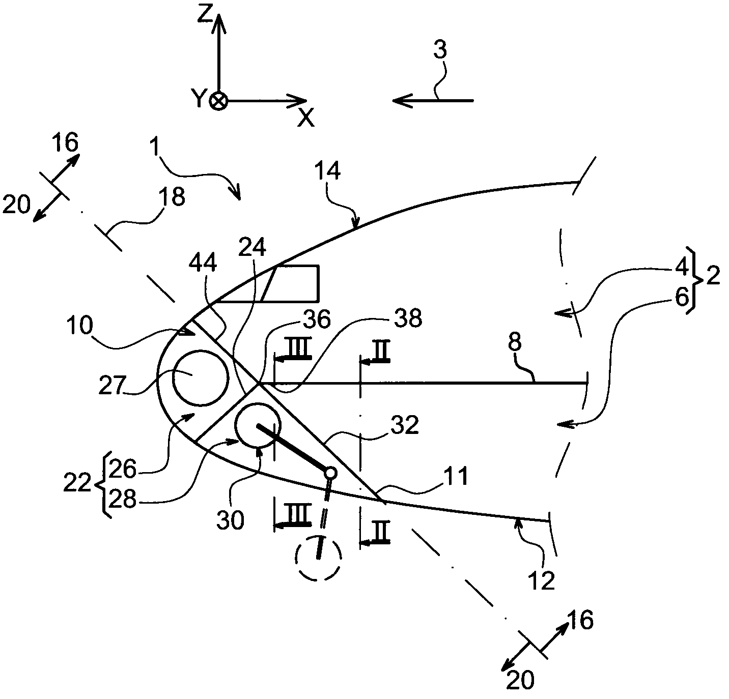
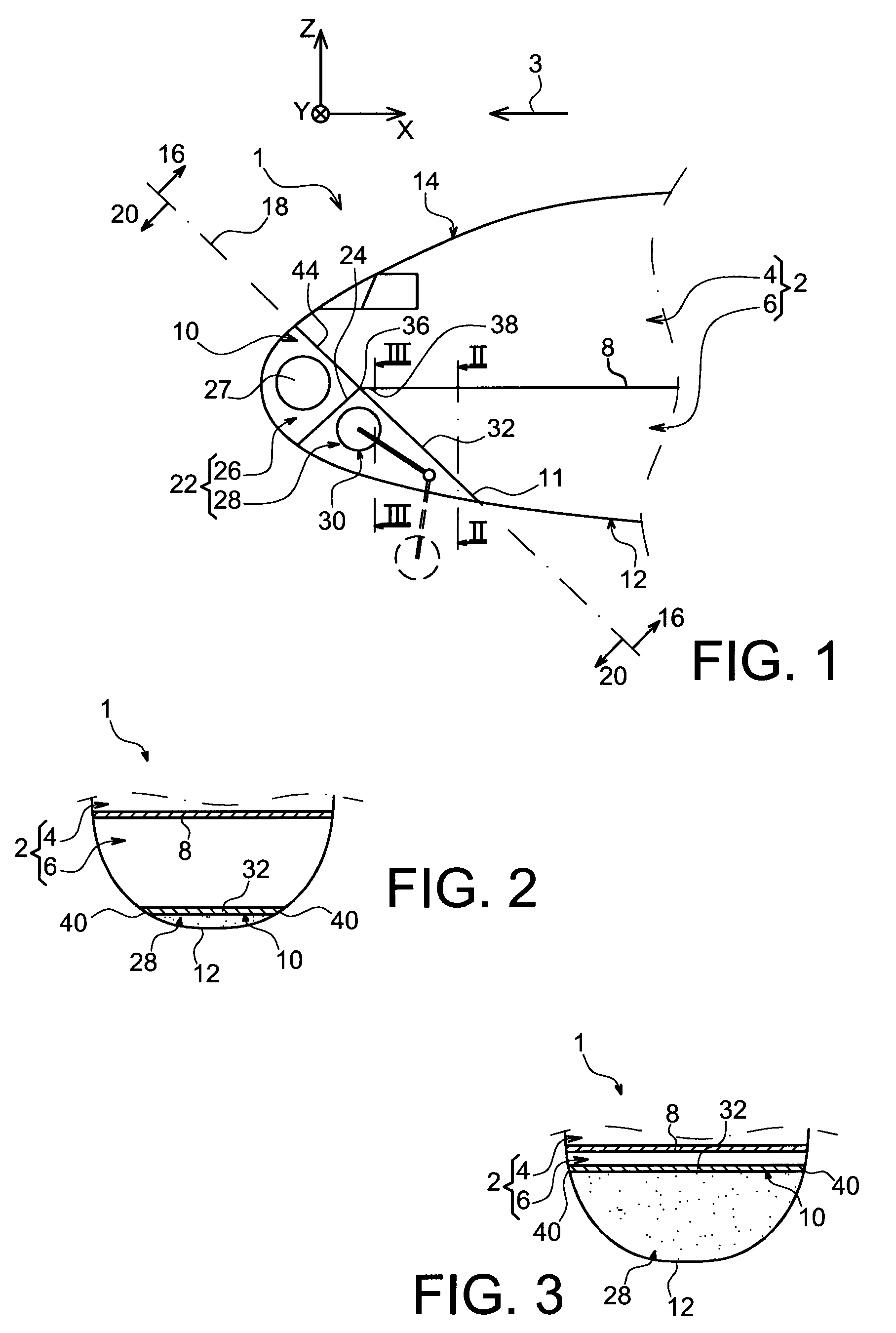
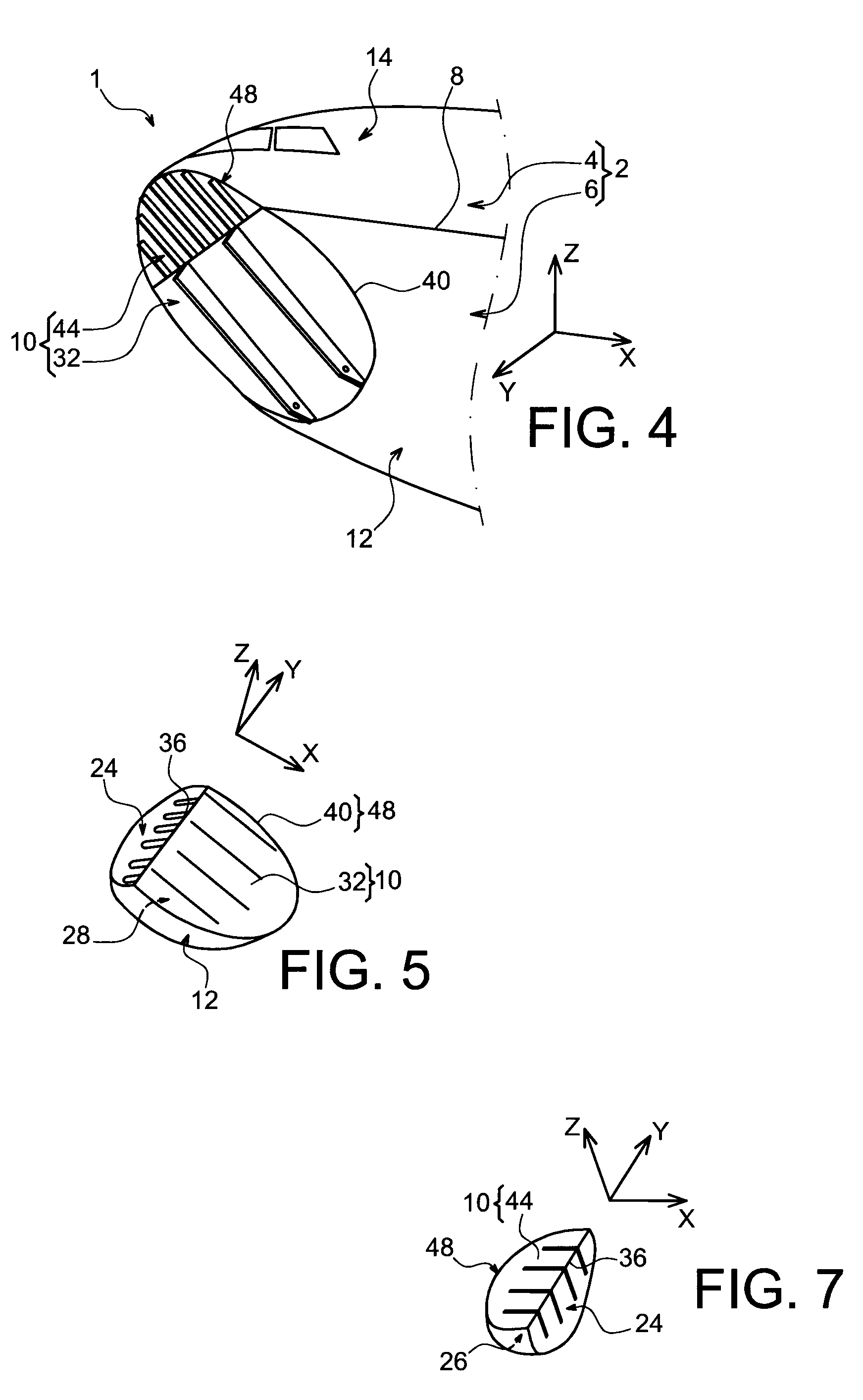
[0035]With reference first of all to FIGS. 1 to 3, a front aircraft part 1 or nose can be seen, according to a preferred embodiment of the present invention.

[0036]Throughout the following description, by convention, the longitudinal direction of the aircraft is referred to as X, the direction oriented transversely with respect to this is Y, and the vertical direction or height is Z, these three directions X, Y and Z being orthogonal to one another.

[0037]In addition, the terms “front” and “rear” are to be considered with respect to a direction of travel of the aircraft encountered following the thrust exerted by the turbojets, this direction being represented schematically by the arrow 3.

[0038]The front part 1 comprises first of all, in its rearmost part, a pressurised zone 2 within which there is situated a separation floor 8 between a top pressurised compartment 4 generally dedicated to the transportation of passengers and an under-floor pressurised compartment 6 normally dedicated...


PUM


Abstract

The present invention relates to a front aircraft part (1) comprising a non-pressurised landing gear housing zone (28) designed to house a front landing gear (30) in a retracted state, as well as a pressurised zone (2) adjacent to the non-pressurised landing gear housing zone. According to the invention, the pressurised zone is delimited by a set of walls among which only a substantially flat-shaped sealed partition wall (10) also participates in delimiting the non-pressurised landing gear housing zone (28).

Description

TECHNICAL FIELD[0001]The present invention relates in general terms to a front aircraft part, also referred to as the nose, of the type comprising a non-pressurised zone for housing the landing gear, designed to house the front landing gear in a retracted state, as well as a pressurised zone adjacent to this non-pressurised zone for housing the landing gear.[0002]The invention is particularly adapted to large capacity and very large capacity commercial aircraft.PRIOR ART[0003]In the prior art, a conventional front aircraft part is known in which the non-pressurised zone for housing the front landing gear, also referred to as the “landing gear compartment”, takes the form of a substantially parallelepipedal space considerably offset towards the rear with respect to a radome area.[0004]The non-pressurised zone housing the front landing gear is therefore located in a lower part of the pressurised zone and separated from this by a plurality of sealed partitions, among which there are tw...

Claims


Application Information

Patent Timeline
Patent Type & Authority Patents(United States)
IPC IPC(8): B64C1/00
CPCB64C1/10B64C1/36B64C25/14
Inventor GUERING, BERNARDGUERING, JONATHAN
Owner AIRBUS OPERATIONS (SAS)
Why Eureka
Try Eureka