Methods for improving flow through fluidic channels

a technology of fluidic channels and ejection actuators, which is applied in printing and other directions, can solve the problems of impeded fluid flow, low surface energy, and misfiring of ejection actuators, and achieve the effects of improving fluid flow, increasing fluid wetting, and increasing the surface energy of one or mor

Active Publication Date: 2010-08-31
FUNAI ELECTRIC CO LTD
View PDF6 Cites 24 Cited by
  • Summary
  • Abstract
  • Description
  • Claims
  • Application Information

AI Technical Summary

Benefits of technology

[0002]Micro-fluid ejecting devices such as ink jet printers continue to be improved as the technology for making the printheads continues to advance. New techniques are constantly being developed to provide low cost, highly reliable printers which approach the speed and quality of laser printers.
[0003]One area of improvement in the micro-fluid ejecting devices is in the ejection head itself. This seemingly simple device is a microscopic marvel containing electrical circuits, fluid passageways and a variety of tiny parts assembled with precision to provide a powerful, yet versatile component of the printer. The components of the ejection head must also cooperate with an endless variety of fluids to provide the desired ejection functions. Accordingly, it is important to match the ejection head components to the fluid and the duty cycle demanded by the ejection application. Slight variations in production quality can have a tremendous influence on the product yield and resulting ejection head performance.

Problems solved by technology

Under high frequency operation, misfiring of the ejection actuators may result if the ejection chambers are not adequately refilled between fluid ejection actuation cycles.
Additionally, flow features having relatively low surface energy are more likely to attract and hold air bubbles which can impede fluid flow.

Method used


Image

  • Methods for improving flow through fluidic channels
  • Methods for improving flow through fluidic channels
  • Methods for improving flow through fluidic channels

Examples


Embodiment Construction

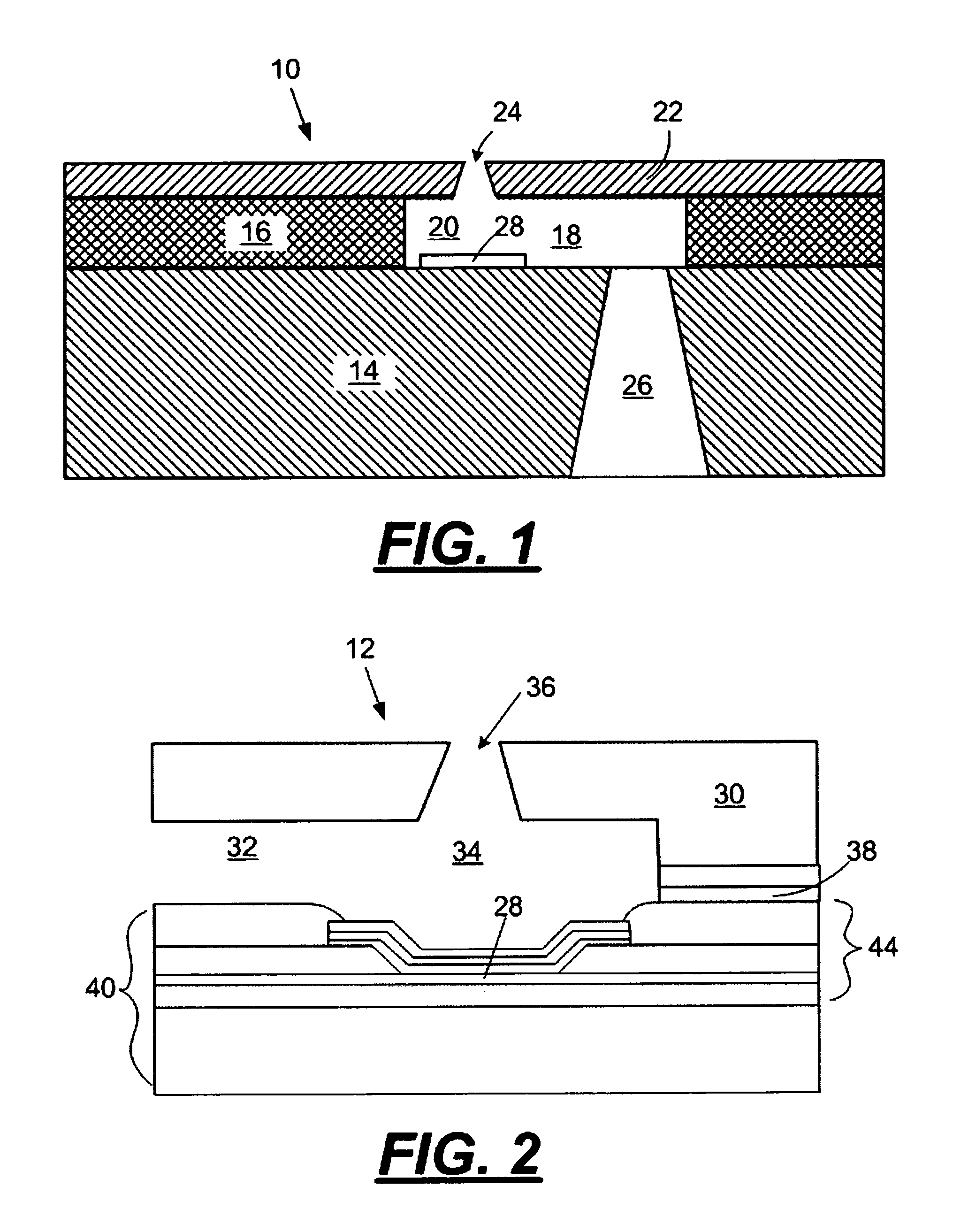
[0020]With reference to FIGS. 1 and 2, cross sectional views, not to scale, of portions of micro-fluid ejection heads 10 and 12 are illustrated. The micro-fluid ejection head 10 includes a substrate, such as semiconductor substrate 14, to which a thick film layer 16 is attached. In the micro-fluid ejection head illustrated in FIG. 1, the thick film layer 16 is made of a photoimageable material that is applied to the substrate 14, that is imaged and developed to provide fluid flow channels 18 and fluid ejection chambers 20. A separate nozzle plate 22 containing nozzle holes 24 is attached to the thick film layer 16. For the purposes of this disclosure, the fluid flow channel 18, the fluid ejection chamber 20, and the nozzle hole 24 are collectively referred to as “flow features.” A fluid supply slot 26 is etched or grit blasted through the substrate 14 to provide fluid flow communication between the flow features and a fluid supply source. A fluid ejection actuator 28 is provided on ...


PUM


Abstract

Methods for improving fluid flow in one or more flow features of a micro-fluid ejection head and micro-fluid ejection heads having improved fluid flow. One method includes bonding a substrate having a flow feature layer to an ejection head body using a relatively low stress, substantially flexible adhesive containing a relatively volatile polar organic compound. The adhesive is cured under conditions sufficient to induce outgassing of at least a portion of the relatively volatile polar organic compound on at least a portion of a flow feature surface sufficient to increase fluid wetting of the flow feature surface.

Description

FIELD OF THE DISCLOSURE[0001]The disclosure is directed to micro-fluid ejecting devices and more specifically to structures and methods for improving fluid flow in a micro-fluid ejection head.BACKGROUND AND SUMMARY[0002]Micro-fluid ejecting devices such as ink jet printers continue to be improved as the technology for making the printheads continues to advance. New techniques are constantly being developed to provide low cost, highly reliable printers which approach the speed and quality of laser printers.[0003]One area of improvement in the micro-fluid ejecting devices is in the ejection head itself. This seemingly simple device is a microscopic marvel containing electrical circuits, fluid passageways and a variety of tiny parts assembled with precision to provide a powerful, yet versatile component of the printer. The components of the ejection head must also cooperate with an endless variety of fluids to provide the desired ejection functions. Accordingly, it is important to matc...

Claims


Application Information

Patent Timeline
Patent Type & Authority Patents(United States)
IPC IPC(8): B41J2/05B41J2/135
CPCB41J2/14129B41J2/1603B41J2/1623B41J2/1626B41J2/1631B41J2/1634
Inventor WEAVER, SEAN T.
Owner FUNAI ELECTRIC CO LTD
Why Eureka
Try Eureka