Signal transmission apparatus of a DC brushless motor for a ceiling fan

a transmission apparatus and dc brushless technology, applied in the direction of motor/generator/converter stopper, machine/engine, dynamo-electric converter control, etc., can solve the problems of high cost, high cost, and high durability of the motor axis, so as to prevent the event of excessively large connecting holes in the motor axis

Active Publication Date: 2010-08-31
RHINE ELECTRONICS
View PDF1 Cites 0 Cited by
  • Summary
  • Abstract
  • Description
  • Claims
  • Application Information

AI Technical Summary

Benefits of technology

[0008]One objective of this invention is to provide a signal transmission apparatus of a DC brushless motor for a ceiling fan, in which the output signal from a sensor is transmitted to a controller via one transmission line. As a result, the number of connecting lines is reduced from five to two. The two connecting lines are the transmission line and reference voltage level line. In this way, the eventual degradation of the motor axis due to excessively large connecting holes is prevented.
[0009]Through the combination of a plurality of output signals from the respective sensors in this invention, the output signals can be transmitted from the sensors mounted in the motor to a controller through just one transmission line. Thus, the number of transmission lines is reduced without affecting the data of such output signals, and therefore. Usage of line materials can be reduced effectively.

Problems solved by technology

However, this is an invasive process that often ends in hardware damage.
These large connecting holes may degrade the durability of the motor axis, and consequently, place the user at risk for injury after a long period of service.

Method used


Image

  • Signal transmission apparatus of a DC brushless motor for a ceiling fan
  • Signal transmission apparatus of a DC brushless motor for a ceiling fan
  • Signal transmission apparatus of a DC brushless motor for a ceiling fan

Examples


Embodiment Construction

[0019]The main concept of this invention is to achieve signal transmission in a DC brushless motor of a ceiling fan using a sequenced signal transmission technology. The following descriptions will be made in reference to the preferred embodiment.

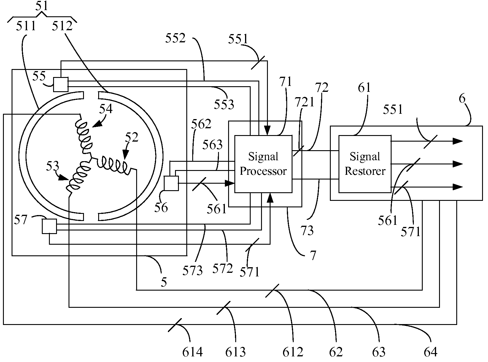
[0020]FIG. 3 illustrates a DC brushless motor 5, a controller 6 and a signal transmission apparatus 7 in a ceiling fan (not shown). The DC brushless motor 5 comprises a magnet 51 with two magnetic poles 511 and 512, three excitation coils 52, 53 and 54, and three sensors 55, 56 and 57. In this embodiment, the sensors are Hall sensors, however, the sensors can be any sensors being able to detect the magnetic pole operations in the DC brushless motor. The controller 6 comprises a signal restorer 61 and three coil-energizing lines 62, 63 and 64 electrically connected to the excitation coils 52, 53 and 54 respectively. The signal transmission apparatus 7 comprises a signal processor 71, a transmission line 72 and a reference voltage level line ...


PUM


Abstract

A signal transmission apparatus of a DC brushless motor for a ceiling fan is provided. The signal transmission apparatus comprises a transmitting line. The transmitting line is configured to transmit processed output signals of a plurality of electromagnetic sensors, in which usage of transmission lines is reduced. The output signals of the electromagnetic sensors represent the operation of the magnetic poles of the DC brushless motor.

Description

RELATED APPLICATION(S)[0001]This application claims the benefit of priority based on Chinese Patent Application Serial No. 200710109643.X, filed 4 Jun. 2007, the contents of which are herein incorporated by reference.BACKGROUND OF THE INVENTION[0002]1. Field of the Invention[0003]The present invention relates to a signal transmission apparatus of a DC brushless motor. More particularly, the present invention relates to a signal transmission apparatus used in a DC brushless motor of a ceiling fan for transmitting at least one processed output signal from at least one sensor, wherein the output signal represents a variation of the magnetic pole operations in the DC brushless motor.[0004]2. Descriptions of the Related Art[0005]DC brushless motors have several advantages, such as a high torque at low speeds and low electromagnetic interference. In addition, they are free of noise and carbon brush maintenance. However, to successfully start and maintain smooth operation of a DC brushless...

Claims


Application Information

Patent Timeline
Patent Type & Authority Patents(United States)
IPC IPC(8): H02P1/46
CPCF04D25/068F04D25/088H02K11/0073H02K29/08H02K11/33
Inventor LIAO, YIN SHENG
Owner RHINE ELECTRONICS
Why Eureka
Try Eureka