Tapping point clearing apparatus

a technology of tapping point and clearing apparatus, which is applied in the direction of cleaning process and apparatus, chemistry apparatus and process, and cleaning hollow objects, etc., can solve the problems of failure of prior art arrangements, and achieve the effect of connecting the shaft and maximising the connection

Active Publication Date: 2016-10-18
CLEARGUARD IPCO
View PDF7 Cites 0 Cited by
  • Summary
  • Abstract
  • Description
  • Claims
  • Application Information

AI Technical Summary

Benefits of technology

[0020]Thus, with the threaded end of the shaft being substantially the same diameter as that of the adjacent shaft, the connection between the shaft and piston is made stronger and less likely to fail under rapid deceleration at the advance and retract stop limits, particularly the advance (extending the clearing head) movement.
[0021]The thread of the threaded first end of the shaft may extend to meet the shafts outer surface at the adjacent intermediate portion, thereby ensuring maximum connection between the threaded first end and remaining shaft. This arrangement avoids thinning the diameter of the shaft between the shoulder formed by the unthreaded intermediate portion of the shaft and the start of the thread at the threaded first end. Prior art arrangements are known to fail at this weakened point.
[0022]The piston may include a through aperture arranged to receive a retaining fastener, the retaining fastener configured to engage with the threaded first end of the shaft within the piston and thereby prevent unthreading of the shaft from the piston until the retaining fastener is released from engagement with the threaded first end of the shaft. The retaining fastener may be threaded, such as in the form of a ‘grub’ screw.
[0025]Thus, the threaded first end of the shaft, and thus the shaft, may be ‘keyed’ by the retaining fastener to prevent the shaft rotating and the cooperating shaft and piston threads separating. The grub screw can thus provide such a key.
[0035]Showing a positive visual indication of the fully or sufficiently advanced and retracted positions of the piston, and therefore the respective positions of the clearing head / tool demonstrates that the ram is operating within required parameters. Furthermore, a positive visual indication that the piston is at an intermediate position allows an operator to positively check operation of the ram, such that the visual indication changes from a first indication to a second indication and then back to the first indication during each of the forward (advance) and rearward (retraction) strokes.

Problems solved by technology

Prior art arrangements are known to fail at this weakened point.

Method used


Image

  • Tapping point clearing apparatus
  • Tapping point clearing apparatus
  • Tapping point clearing apparatus

Examples


Embodiment Construction

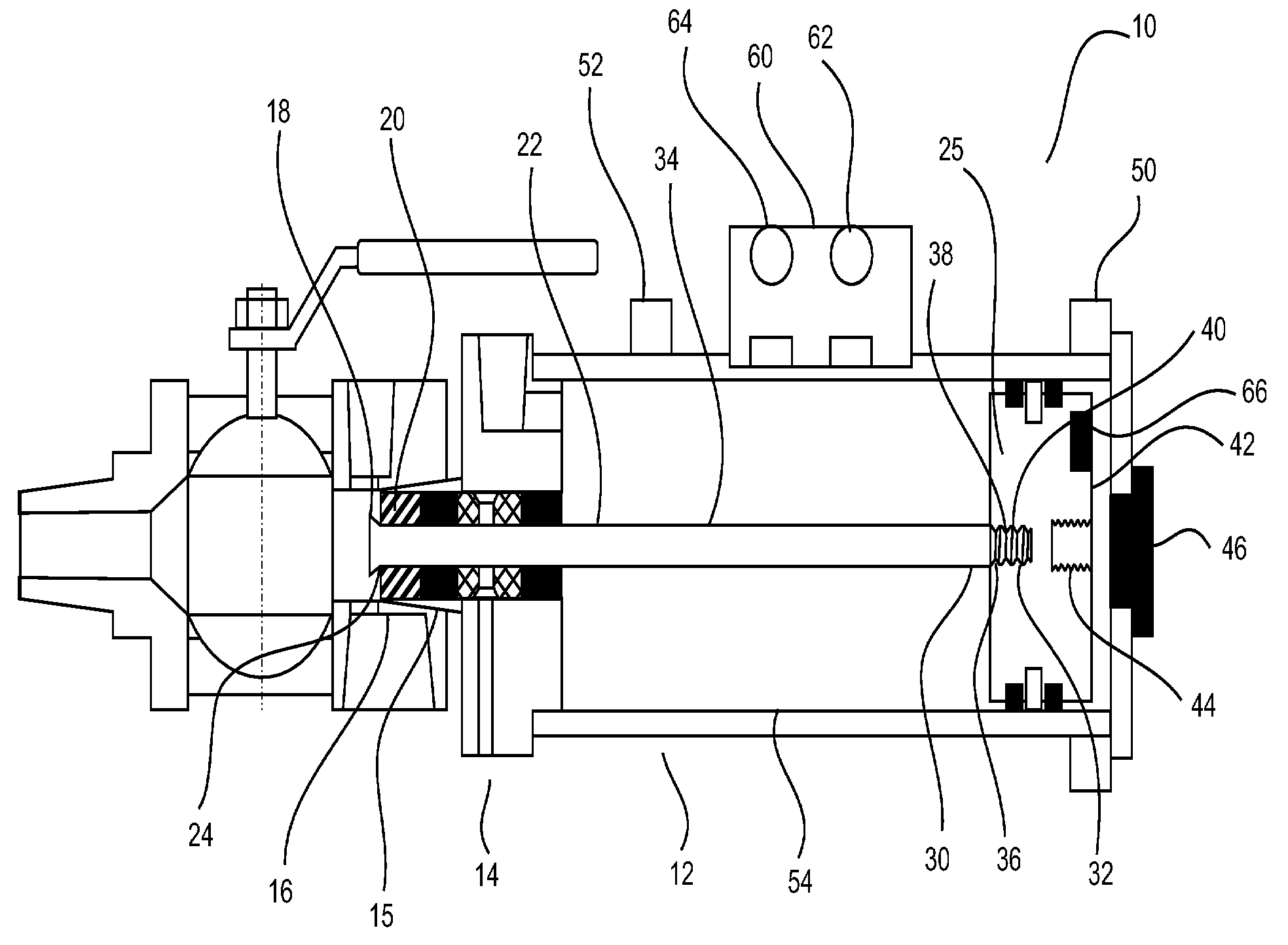
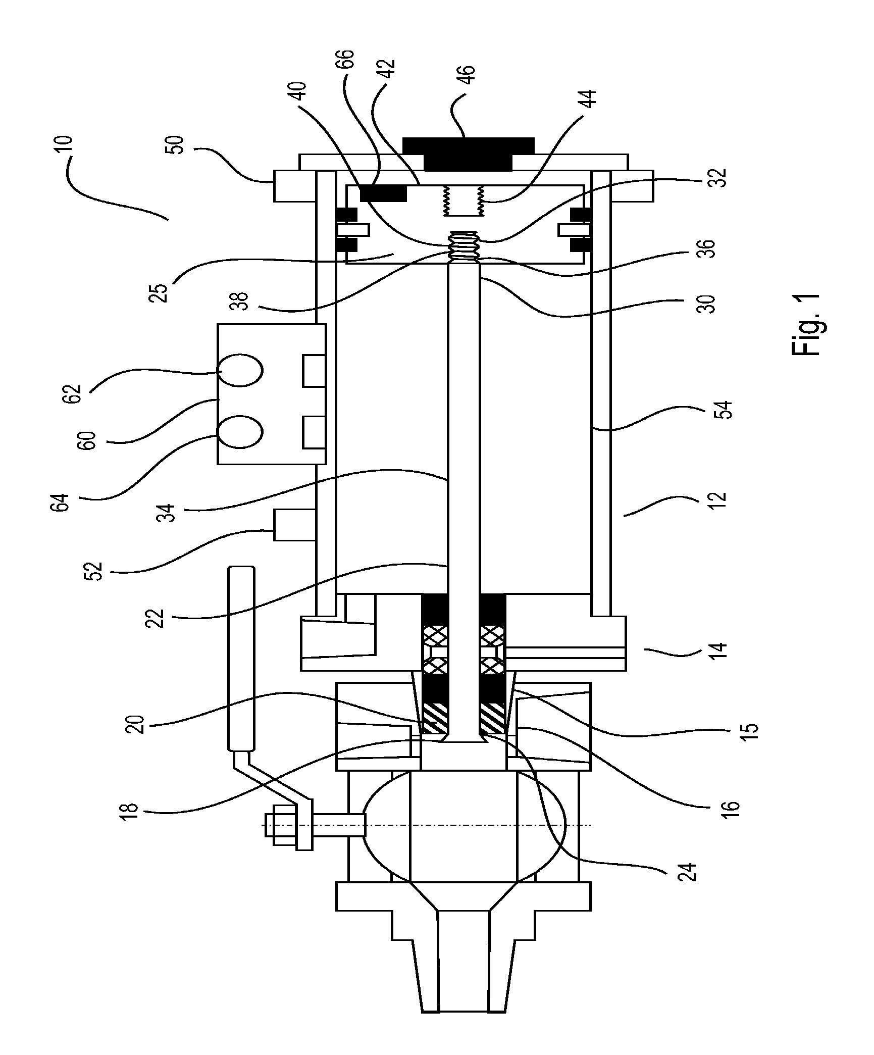
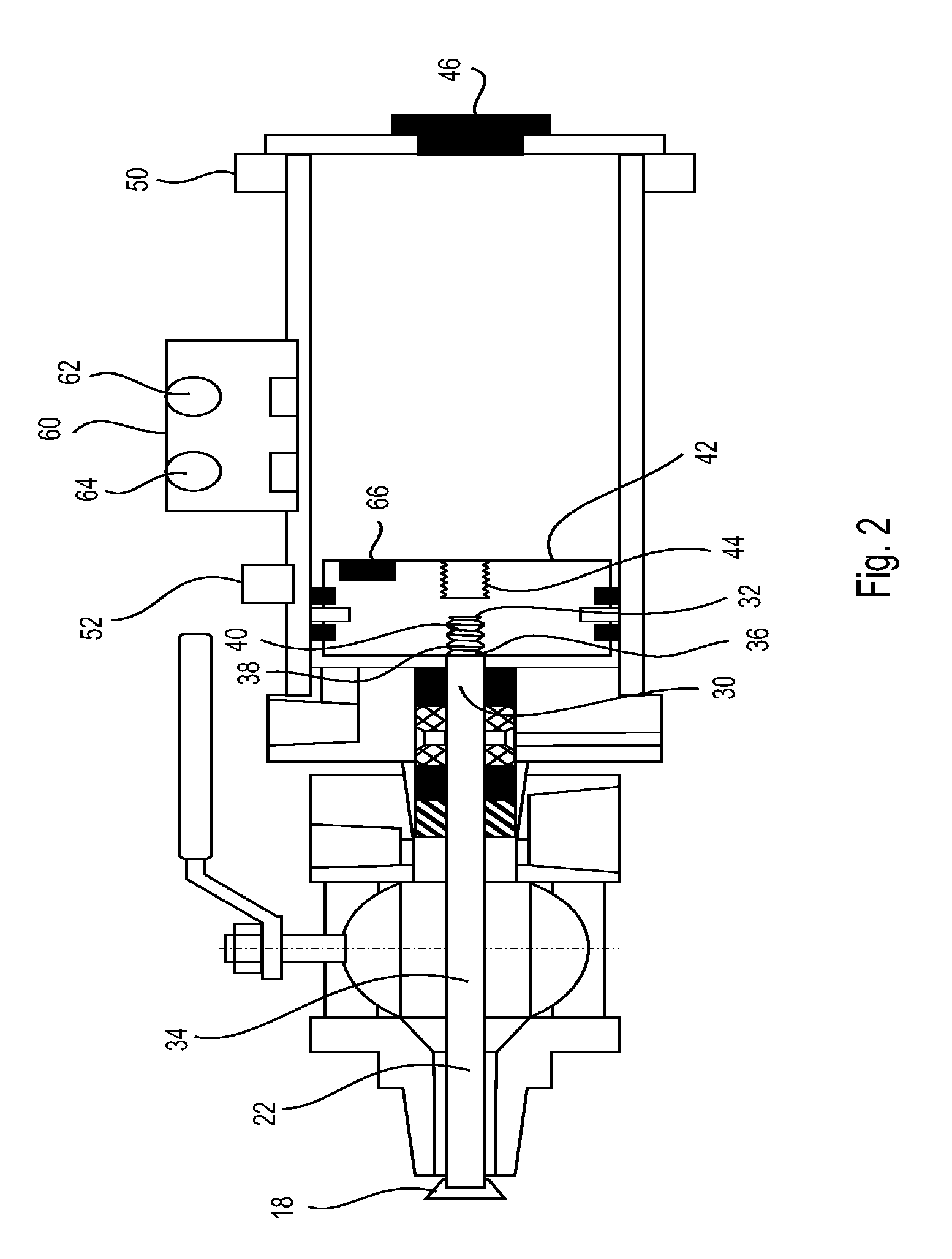
[0044]FIG. 1 shows a process tapping point clearing apparatus 10. The apparatus 10 includes a pneumatic cylinder 12, which is axially mounted by suitable means such as a flanged connection to a head portion 14. The head portion 14 includes a housing 15 having an outer, externally threaded portion 16 arranged to engage within a tapping point (Generally behind an isolation valve in a process vessel, pipeline or similar.

[0045]A clearing tool 18 extends from a front end 20 of the housing 15. The clearing tool 18 is axially mounted to a reciprocating shaft 22. The shaft 22 extends through an aperture 24 in the front end 20 of the housing 15, through the head portion 14 and into the cylinder 12. Axial movement of the shaft 22 causes the clearing tool 18 to move through the process vessel tapping point, clearing the tapping point of accumulated debris.

[0046]The shaft 22 is mounted to a piston 25 within the cylinder 12. Supply of compressed air through a respective connection (not shown) re...


PUM


Abstract

A process tapping point clearing apparatus (10) has a ram housing a piston (25) in a cylinder (12). A piston shaft (22) has a threaded first end (30) threadingly engaged with the piston. A second end of the shaft retains a clearing head extending from the cylinder, the clearing head adapted to pass through a process tapping point for removing scaling and / or debris material therefrom. The threaded first end of the shaft has an outer thread (36) diameter substantially the same as the diameter of the adjacent intermediate portion of the shaft. The piston can have a threaded aperture (44) to receive an release tool (45) to retract the piston and tapping point clearing toll (34) if stuck in an extended position.

Description

FIELD OF THE INVENTION[0001]The present invention relates to improvements to apparatus for clearing process tapping points in industrial and mineral processing operations. Such tapping points are generally used within process measurement systems.BACKGROUND TO THE INVENTION[0002]The processing industry relies upon the accurate measurement of process variables to enable efficient control of industrial processes. One of the most common methods of taking various process measurements is via process tapping points exposed to the interior contents of a process vessel or pipeline. Flow and / or pressure through an internal bore of the tapping points is indicative of certain process variables.[0003]Such tapping points encounter progressive scaling or debris build-up over time within their internal bores. The restriction or blockage of process tapping points by scaling or debris build-up can cause inaccurate process measurement, inaccurate product sampling or even render the process measurement...

Claims


Application Information

Patent Timeline
Patent Type & Authority Patents(United States)
IPC IPC(8): B08B9/043B08B1/00B08B9/00
CPCB08B9/0436B08B1/008B08B9/00
Inventor SAUER, HANS ERNSTPETTERSSON, CARL JAMES
Owner CLEARGUARD IPCO
Why Eureka
Try Eureka