Connection element and method for introducing a connection element

a technology of connection elements and connection elements, which is applied in the direction of threaded fasteners, manufacturing tools, other domestic articles, etc., can solve the problems of insufficient fastening of hollow chamber components, and the requirement of cost-effective connection elements

Active Publication Date: 2022-08-16
EJOT GMBH & CO KB
View PDF25 Cites 0 Cited by
  • Summary
  • Abstract
  • Description
  • Claims
  • Application Information

AI Technical Summary

Benefits of technology

[0007]The invention is therefore based on the object of providing a connection element to be introduced into hollow chamber components which can be permanently and securely fastened in hollow chamber components, wherein the connection element is able to be manufactured inexpensively.
[0009]The connection element is advantageously designed to be essentially rotationally symmetrical and in the main part has a tool placement point for transmitting a torque in the region on the upper face. This makes it possible to apply an axial force in the direction of the longitudinal axis to the connection element to be introduced into a hollow chamber component and at the same time to drive it in rotation about the longitudinal axis.
[0016]Another particularly advantageous further development of the connection element is characterized in that the metallic sleeve has a plasma-treated surface and is at least partially encapsulated with the thermoplastic synthetic material of the main part. It is particularly preferred if the surface of the sleeve is plasma-nitrided. The adhesion of the thermoplastic synthetic material to the metallic sleeve can thus be improved. As an alternative or in addition to this, it is conceivable that the sleeve has a non-circular-cylindrical region which protects the sleeve in the thermoplastic synthetic material against twisting, for example a square or hexagonal head. However, it is also conceivable that a knurl, ribbing and / or grooving is provided on the surface of the sleeve. The introduction of ribs, grooves or a knurl, as well as the use of a square or hexagonal head, however, lead to overall comparatively large connection elements due to the necessary wall thicknesses of the sleeve and the dimensions of the square or hexagonal head. A plasma treatment of the surface has consequently proven to be particularly advantageous, because metallic sleeves having a comparatively thin wall thickness can be used.
[0020]The object mentioned at the outset is also achieved by a method having the features of claim 11 for introducing a connection element according to any of claims 1 to 10 into a hollow chamber component, in particular a plate-shaped hollow chamber component which has hollow chambers. The method is characterized by rotationally driving the connection element about its longitudinal axis and applying an axial force along the longitudinal axis of the connection element in the direction of the hollow chamber component by means of a tool, so that the thermally activatable expandable material extends due to heat generated by friction between the connection element and the hollow chamber component, in particular in hollow chambers of the hollow chamber component. A pre-punching of the hollow chamber component can thus be avoided.
[0023]Furthermore, it is advantageous if the tool applies an axial force in the range of from approximately 800 N to approximately 1,200 N, preferably approximately 1,000 N, to the connecting means.

Problems solved by technology

When connection elements known from the prior art are introduced, it has been shown that their fastening in the hollow chamber components is in some cases insufficient, so that the connection elements have become detached from the hollow chamber components again.
On the other hand, due to the often large number of connections in aircraft construction, a cost-effective connection element is required.

Method used


Image

  • Connection element and method for introducing a connection element
  • Connection element and method for introducing a connection element
  • Connection element and method for introducing a connection element

Examples


Embodiment Construction

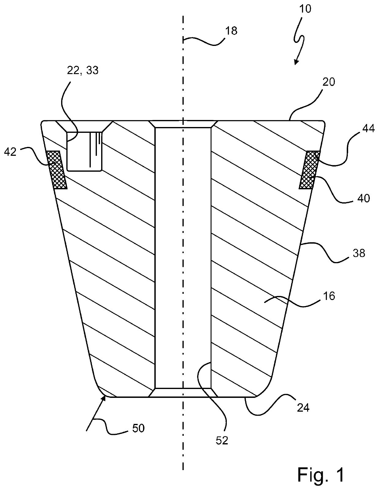
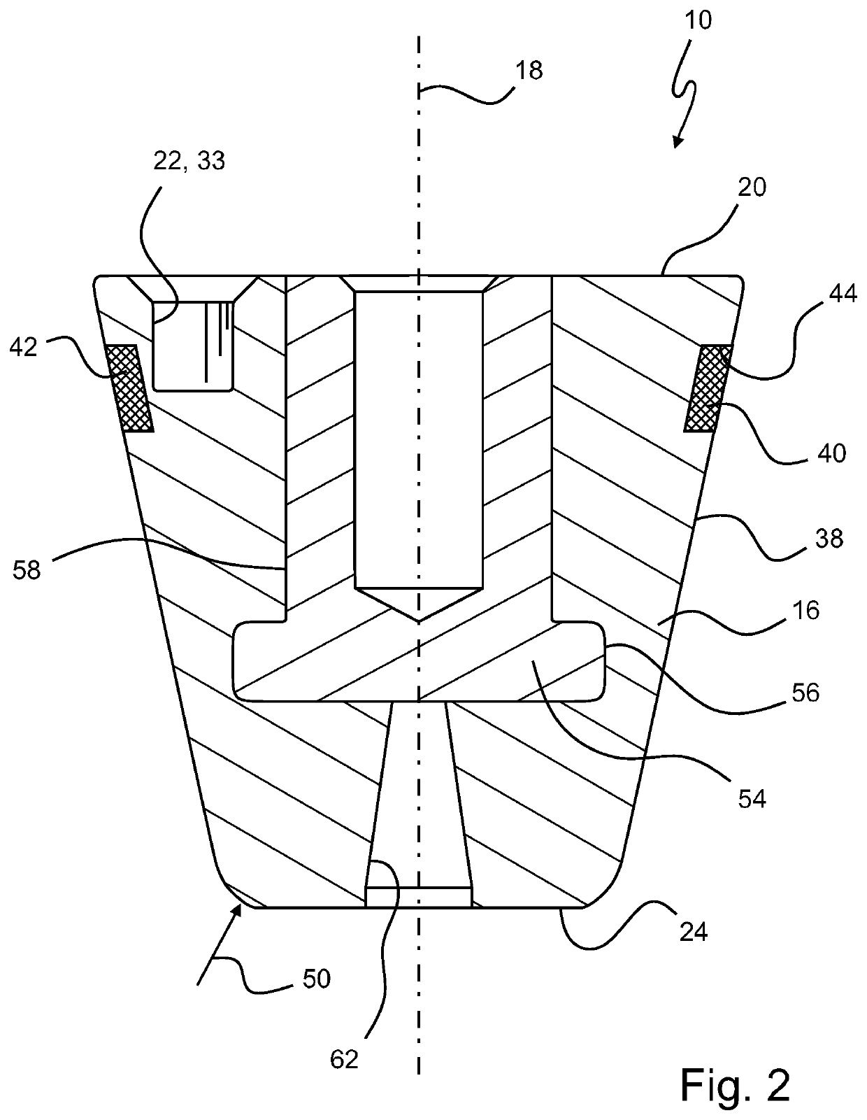
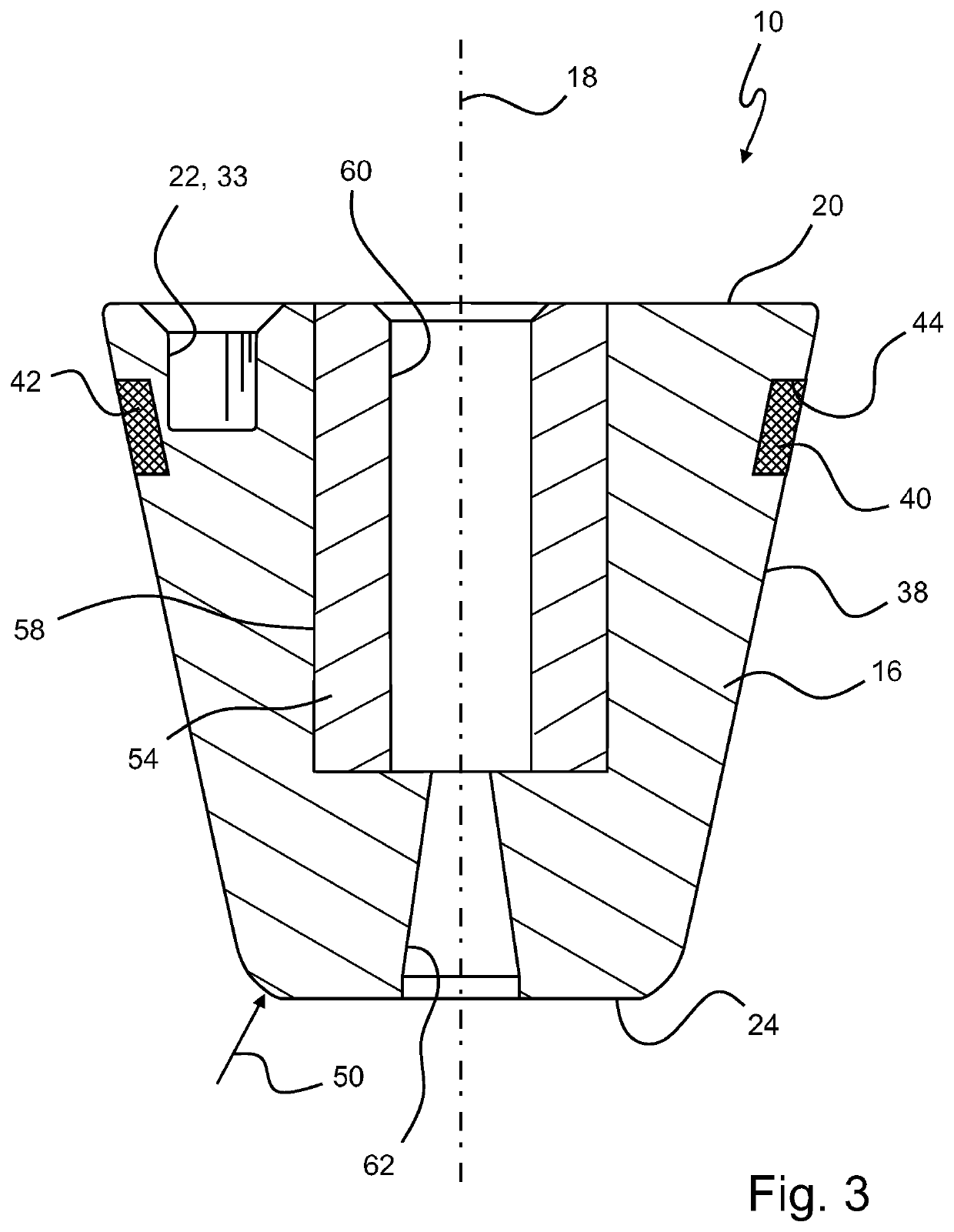
[0033]In FIGS. 1 to 4, various embodiments of a connection element 10 according to the invention are shown in section along the line A-A according to FIG. 5. Corresponding elements are identified by the corresponding reference symbols.

[0034]Connection elements 10, shown schematically in FIG. 6 and also referred to as thermal adhesive bonding boss, are known in the art which are designed to be introduced into a plate-shaped hollow chamber component 14 which has hollow chambers 12 under the effect of pressure and rotation.

[0035]The connection elements 10 are designed to be essentially rotationally symmetrical and have a main part 16 which comprises a thermoplastic synthetic material. The connection elements 10 also have a longitudinal axis 18 and are designed for rotation about the longitudinal axis 18. The connection elements 10 have an upper face 20 with a tool placement point 22 for the transmission of torque, and a lower face 24 facing away from the upper face 20.

[0036]In particul...


PUM

PropertyMeasurementUnit
radiusaaaaaaaaaa
axial forceaaaaaaaaaa

Abstract

The invention relates to a connection element, in particular a thermal adhesive bonding boss, to be introduced into at least one component, in particular a hollow chamber component, in particular a plate-shaped hollow chamber component which has hollow chambers, under the effect of pressure and rotation, comprising a main part which comprises a thermoplastic synthetic material. The connection element has a longitudinal axis and is designed to rotate about the longitudinal axis, and the connection element has an upper face with a tool placement point and a lower face which faces away from the upper face, wherein the connection element has an expanding portion made of a thermally activatable expandable material on the main part on a circumferential surface extending between the upper face and the lower face.

Description

CROSS-REFERENCE TO RELATED APPLICATION[0001]The present application is the U.S. National Stage Application of International Application No. PCT / EP2019 / 067514 filed Jul. 1, 2019, which relates and claims priority to German Application No. 10 2018 117 370.9, filed Jul. 18, 2018, the entire contents of each of which are hereby incorporated by reference.BACKGROUND[0002]The invention relates to a connection element, in particular a thermal adhesive bonding boss, to be introduced into at least one component, in particular to be introduced into a hollow chamber component, in particular a plate-shaped hollow chamber component which has hollow chambers, under the effect of pressure and rotation, comprising a main part which comprises a thermoplastic synthetic material, wherein the connection element has a longitudinal axis and is designed to rotate about the longitudinal axis, wherein the connection element has an upper face with a tool placement point and a lower face which faces away from ...

Claims


Application Information

Patent Timeline
Patent Type & Authority Patents(United States)
IPC IPC(8): F16B5/01B29C44/12B29C65/06B29C65/00F16B13/02F16B37/06B29K105/04F16B1/00
CPCB29C44/1228B29C65/069B29C65/0672B29C66/474B29C66/71B29C66/72525B29C66/7392F16B5/01F16B13/02F16B37/061B29K2105/048F16B2001/0078Y10S411/903F16B2200/97B29K2077/00B29C44/12B29C44/1242B29C66/72321B29C66/712B29L2031/7278B29K2023/12B29K2101/12
Inventor KITTEL, DIETER
Owner EJOT GMBH & CO KB
Why Eureka
Try Eureka