
Device for swinging a wiper arm of a windscreen wiper assembly away from and against a motor vehicle windscreen

a technology for windshield wipers and devices, which is applied in vehicle maintenance, vehicle cleaning, domestic applications, etc., can solve problems such as the moment of swing, and achieve the effects of reducing tool wear and material waste, and simplifying assembly

Inactive Publication Date: 2010-09-07
ROBERT BOSCH GMBH
View PDF7 Cites 33 Cited by
  • Summary
  • Abstract
  • Description
  • Claims
  • Application Information

AI Technical Summary

Benefits of technology

[0003]The objective of the invention is improving the device mentioned at the outset such that in the future assembly is simplified and tool wear and material waste are reduced.
[0004]The invention attains the stated objective via a device of the type mentioned at the outset in which, in accordance with the invention, at least one of the two spring elements has at least one compressed region. As a result, in the future the device can be punched out of sheet metal as a single part, wherein the spring elements are permanently connected on both ends to the connecting elements connecting the spring elements. Therefore, the spring elements now no longer must be fastened to the connecting element on one of their ends via the extra assembly that was previously required. In order to generate the swivel moment that is required for the device's function, at least one of the at least two spring elements is compressed in a selected region. In doing so, the extent of the compression determines the level of the desired swivel moment or the desired pressure force of the wiper arm against the vehicle window. The compressed regions are meaningfully situated at the end of the spring elements since greater stress occurs in the center of the spring elements because of the bending load. Since in the future the device will be punched as a single piece out of the sheet metal, and the spring elements no longer project in a V-shaped manner, in the future less material waste will be incurred. For that reason, material waste as well as tool wear is distinctly reduced.
[0005]In the case of a preferred embodiment, the device comprises two spring elements arranged next to one another, each of which is connected with one another on their end regions by connecting elements, wherein at least one end region of the device and at least one partial region of the connecting elements are compressed. As a result, the compression in at least one end region of the spring elements and in one partial region of the connecting elements generates a force, which attempts to spread the two spring elements. However, since the spring elements are permanently connected on their two ends to the connecting elements, a torsional force is generated in the spring elements, which in turn generates a swivel moment. As a result, it is possible to swivel a wiper arm equipped with the device into a stable position away from the vehicle window. If the wiper arm is swiveled from the swung-out position toward the window, it is swiveled over a critical point at which the swivel moment is turned in the opposite effective direction. Then the wiper arm equipped with the device in accordance with the invention is pressed against the window, thereby achieving optimum wiper performance.

Problems solved by technology

However, since the spring elements are permanently connected on their two ends to the connecting elements, a torsional force is generated in the spring elements, which in turn generates a swivel moment.

Method used


Image

  • Device for swinging a wiper arm of a windscreen wiper assembly away from and against a motor vehicle windscreen
  • Device for swinging a wiper arm of a windscreen wiper assembly away from and against a motor vehicle windscreen
  • Device for swinging a wiper arm of a windscreen wiper assembly away from and against a motor vehicle windscreen

Examples


Embodiment Construction

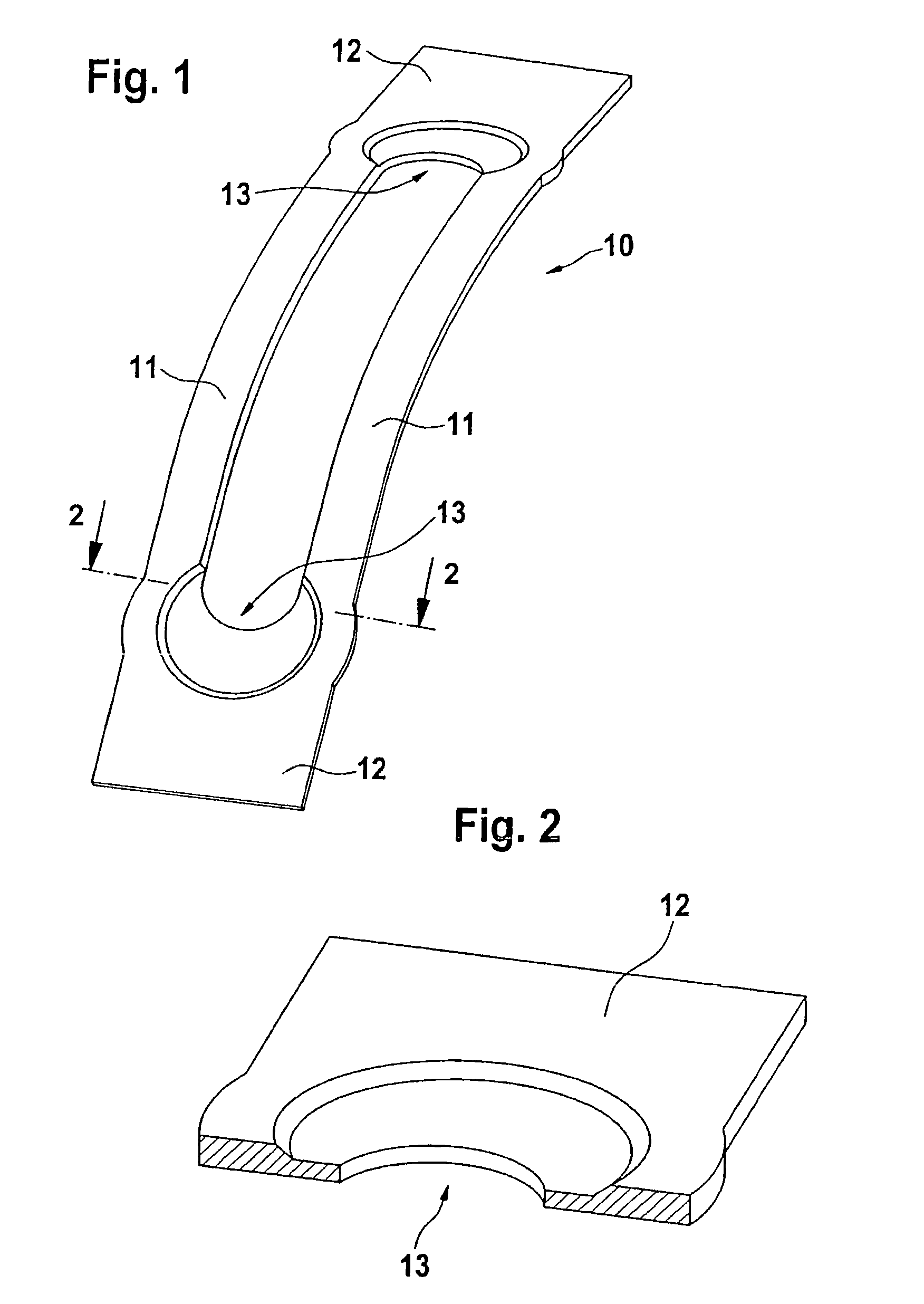
[0016]FIG. 1 shows a device 10 of a wiper arm (not shown in detail here) of a windshield wiper device of a motor vehicle. The device 10 features two spring elements 11, each of which is connected with one another at connecting elements 12. The device 10 has a compressed region 13 in both its ends regions, in which an end region of the spring elements 11 and a partial region of the connecting elements 12 are respectively compressed (also see FIG. 2). Because of the compression in the end region 13, a spreading force is exerted on the spring elements 11, which attempts to spread the spring elements 11 in the end region 13 apart. However, since the spring elements 11 are permanently connected to the connecting elements 12, the spring elements 11 cannot spread apart so that they twist in order to yield to the spreading force. The torsional force acting in the spring elements 11 generates a swivel moment in the device 10, whereby a wiper arm provided with the device 10 can be swung away ...


PUM


Abstract

Device (10) for swinging a wiper arm of a windshield wiper device away from and against a motor vehicle window, wherein the device (10) comprising at least two spring elements (11), which retain the wiper arm in a stable position away from the vehicle window and press the wiper arm against said vehicle window during the operation of the wipers, wherein at least one of the at least two spring elements (11) comprises at least one compressed region (13).

Description

BACKGROUND OF THE INVENTION[0001]The invention relates to a device for swinging a wiper arm of a windshield wiper device away from and against a motor vehicle window, wherein said device comprising at least two spring elements, which retain the wiper arm in a stable position away from the vehicle window and press the wiper arm against said vehicle window during the operation of the wipers.[0002]Non-articulated wiper arms, which are equipped with the device mentioned at the outset instead of articulation, are known form the prior art. In this case, a differentiation is made between essentially two designs. A first design has two spring elements arranged next to each other. The two spring elements are arranged with their one end in a V-shaped manner on a common one-piece connecting element. One portion of a two-part connecting element is respectively attached on the other end of one of the spring elements. During assembly, the spring elements that are arranged in a V-shape manner are ...

Claims


Application Information

Patent Timeline
IPC IPC(8): B60S1/34
CPCB60S1/34B60S1/344B60S1/3475
Inventor WEILER, MICHAELZIMMER, JOACHIM
Owner ROBERT BOSCH GMBH
Features
  • Generate Ideas
  • Intellectual Property
  • Life Sciences
  • Materials
  • Tech Scout
  • Unparalleled Data Quality
  • Higher Quality Content
  • 60% Fewer Hallucinations
Learn More