
Dual chamber aerosol container

a technology of aerosol container and spray bottle, which is applied in the direction of liquid dispensing, liquid transferring device, packaging, etc., can solve the problems of short shelf life of propellant and active composition when mixed, inert ergonomic design for consumers, and more ergonomics, etc., to achieve excellent mixing and dispensing of propellant, simple design, and convenient use.

Inactive Publication Date: 2010-09-07
THE CLOROX CO
View PDF60 Cites 49 Cited by
  • Summary
  • Abstract
  • Description
  • Claims
  • Application Information

AI Technical Summary

Benefits of technology

The present invention provides an aerosol spray dispenser and method of operation that can mix and dispense propellant and active compositions that are not compatible with each other. The dispenser has a simple design and can isolate the propellant chamber from the active composition chamber. It can be used in a refillable or cartridge fashion and can contain a second active composition that is incompatible with the first active composition. The dispenser can minimize the effects of incompatibility between the compositions and can be used to disperse a variety of compositions.

Problems solved by technology

For example, the propellant and active composition when mixed may have a short shelf life after mixing.
This is convenient because of its versatility in attachment and has found commercial use, but it is not ergonomically designed for consumers because of its tall design.
This design is more ergonomic, however, it still suffers from the fact that the dip tube runs through the middle of the propellant chamber.
The active composition may be corrosive and because the propellant chamber is under pressure and frequently made of metal, it is susceptible to pinhole leaks from corrosion.
The designs from both U.S. Pat. No. 6,394,364 and U.S. Pat. No. 3,451,591 do not solve this problem and additionally they do not have the consumer convenience of the Preval® attachment mechanism.

Method used


Image

  • Dual chamber aerosol container
  • Dual chamber aerosol container
  • Dual chamber aerosol container

Examples


Embodiment Construction

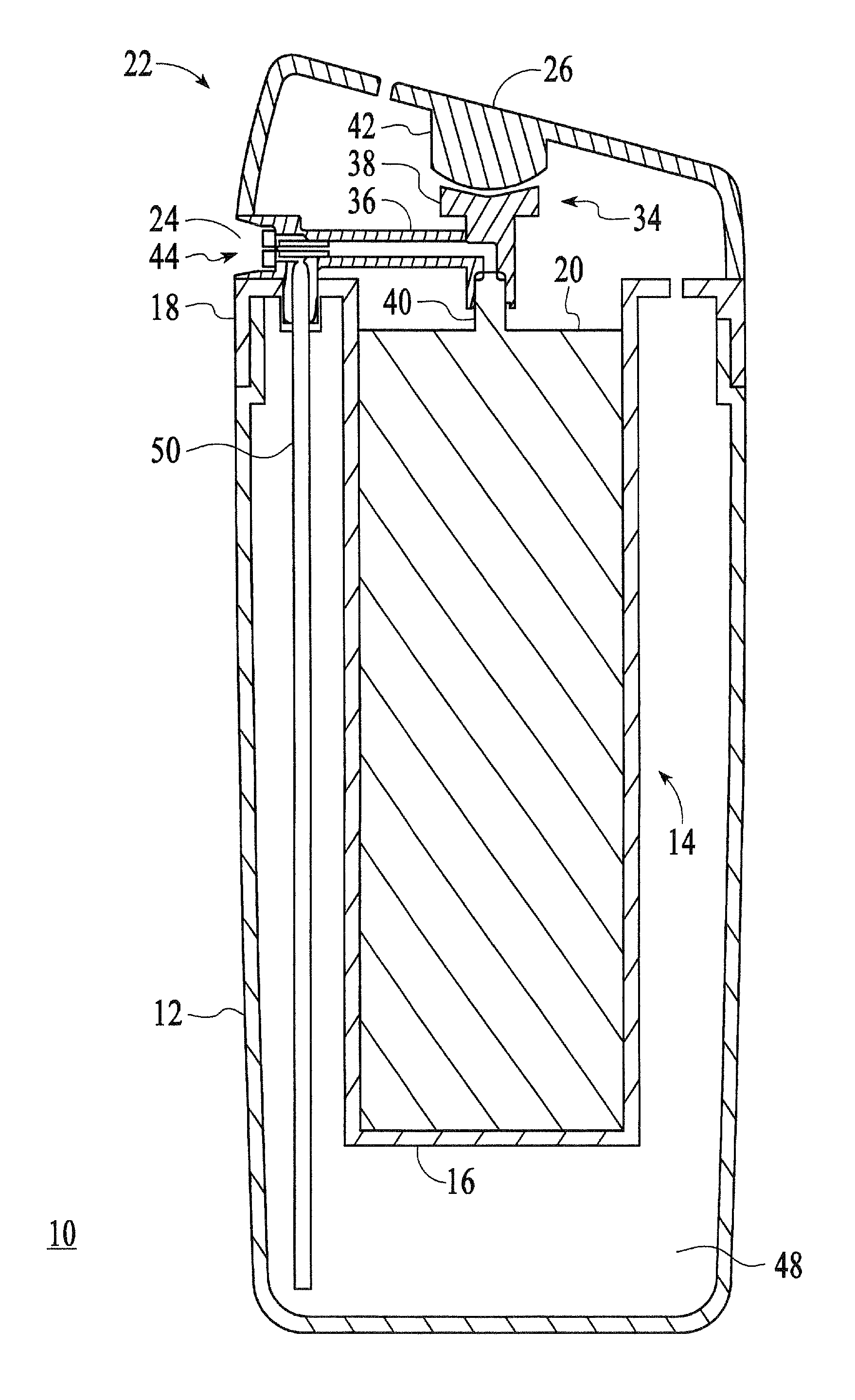
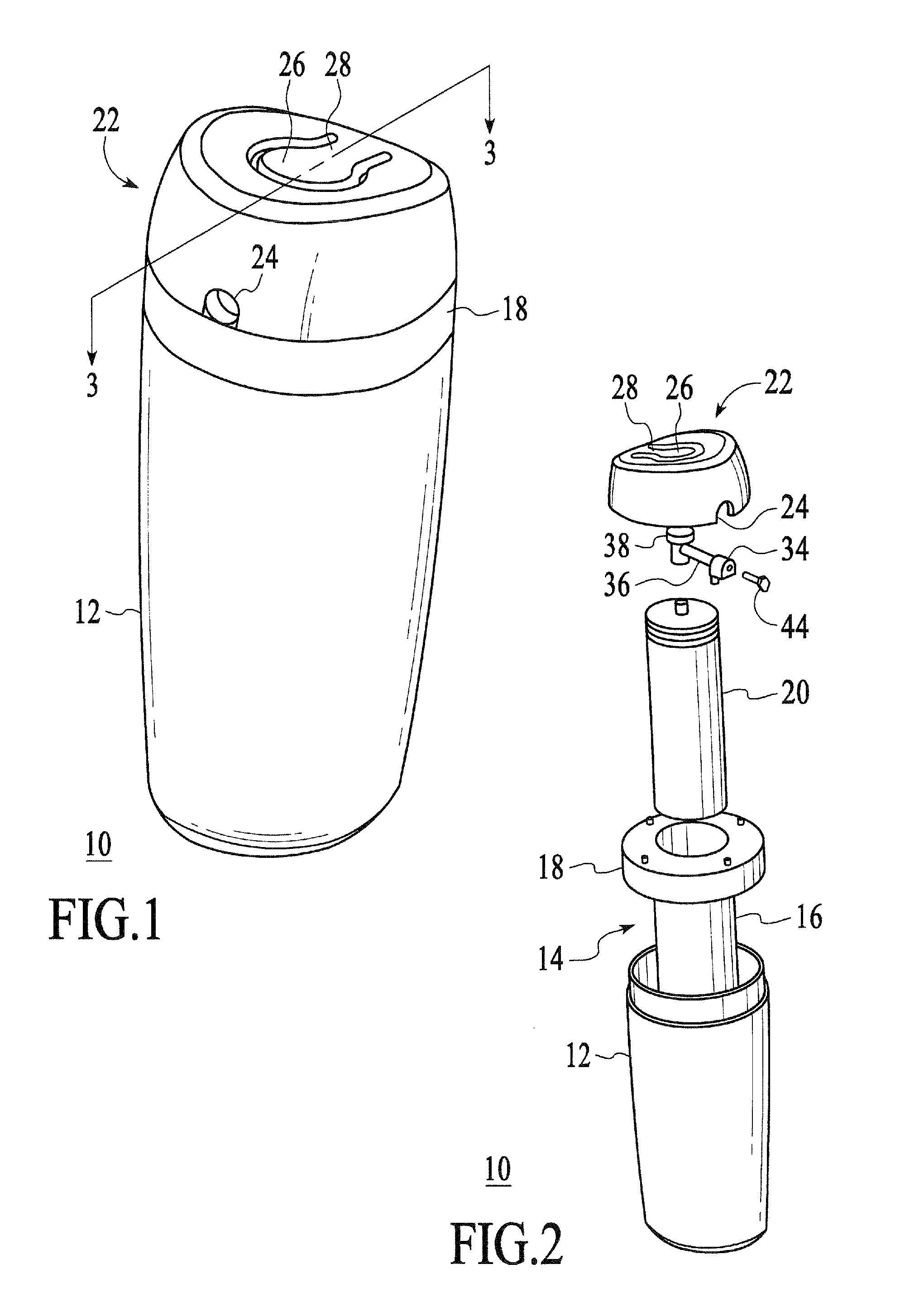
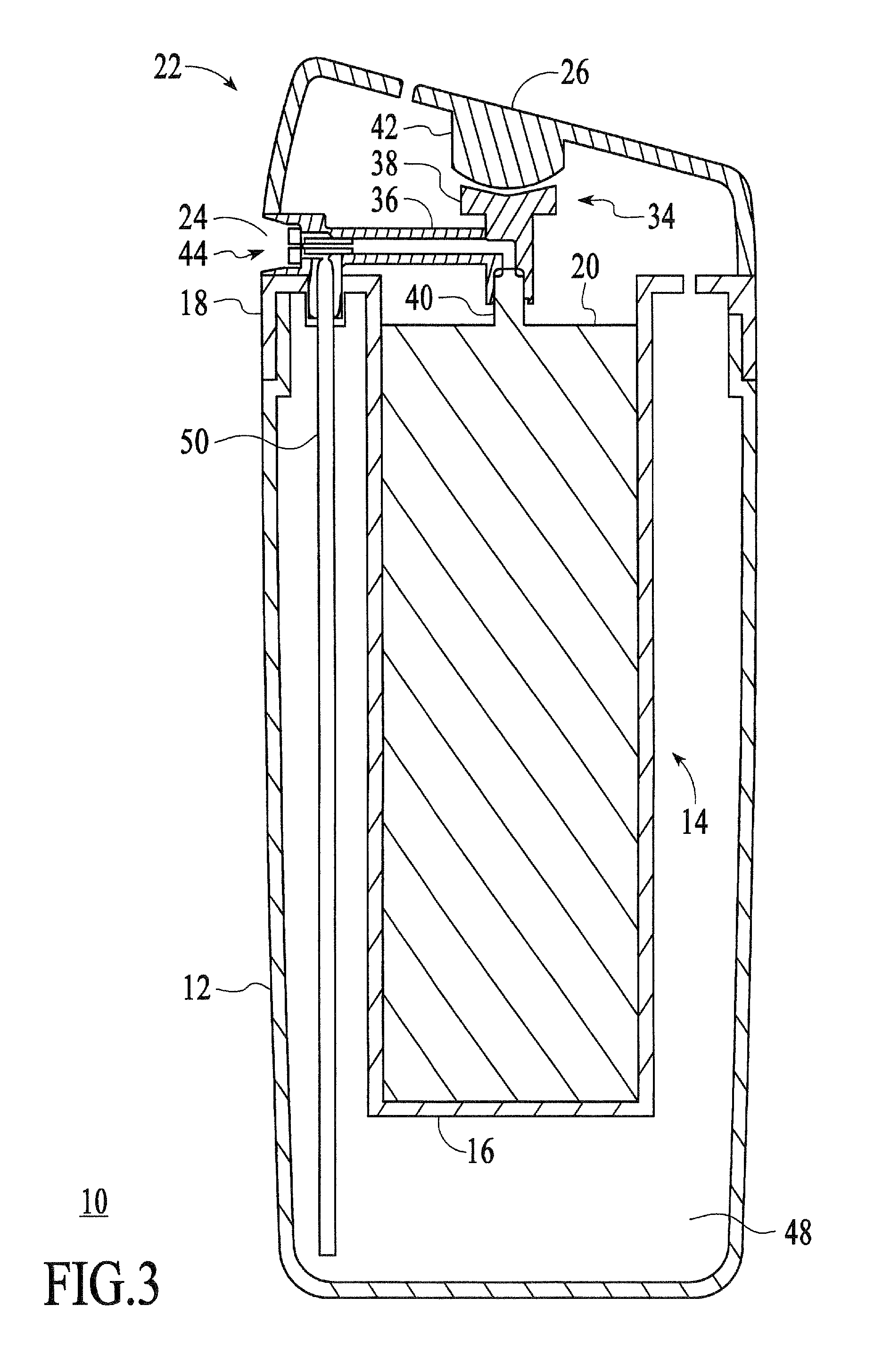
[0019]FIGS. 1 and 2 illustrate the major components of an embodiment of an aerosol dispenser 10 in accordance with the present invention. An outer housing 12 has a bottle or can-shaped configuration. Arranged concentrically within the outer housing is an inner housing or sleeve 14, which has a propellant receptacle containing portion 16 as will be described subsequently. Inner housing 14 also has formed therein a closure cap 18, which encloses and seals the outer housing 12. An aerosol container or receptacle 20 fits within the portion 16 of the inner housing 14.

[0020]Affixed to the closure cap 18 is an overcap assembly 22 that has an opening 24 through which mixed compositions in the form of a spray are dispensed. Formed in the overcap assembly 22 is a manual actuator or button 26 that is formed by cutting a keyhole shaped slit 28 in the top of the cap 18.

[0021]Referring additionally to FIGS. 3 and 4, actuator assembly 34 has a conduit 36 that passes through a responder portion 38 ...


PUM


Abstract

An aerosol spray dispenser is disclosed that includes an outer housing that is circular, oval, or non-oval and in which an active composition to be dispensed is provided and a closure sleeve housing within the outer housing. An inner receptacle is provided within the closure sleeve housing and within the volume of the outer housing and contains a propellant to be dispensed. The inner housing may be concentrically located within the outer housing. An actuator assembly houses a nozzle that has a venturi constriction. A tube extends within the outer housing to provide the passage of active composition from within the outer housing by the venturi effect. A conduit for the passage of a propellant from the inner receptacle to the nozzle is provided. The propellant and the active composition are mixed and dispensed as a spray at a nozzle by action of the venturi effect. Materials that are not compatible with the active composition can be added to the propellant and effectively mixed and dispensed, for example a fragrance that is incompatible with hypochlorite or one component or a two part hardening composition.

Description

BACKGROUND OF THE INVENTION[0001]1. Field of the Invention[0002]The present invention relates to an aerosol spray bottle having an ergonomic design for dispensing an active composition or mixtures.[0003]2. Description of the Related Art[0004]Aerosol sprayers have some form of lever or button typically operated by the finger or hand of the user, to dispense an active composition and propellant from the container. The active composition can be in the form of a spray, stream, or foam. Most aerosol sprayers have one chamber containing both the propellant and the active composition. Some aerosol sprayers dispense the propellant and the active composition from separate containers. In this case, the actual mixing of the propellant and active composition occurs at different locations relative to the output nozzle depending upon the dispenser design. It is most advantageous to create the mixing right at or before the nozzle. For example, the propellant and active composition when mixed may h...

Claims


Application Information

Patent Timeline
Patent Type & Authority Patents(United States)
IPC IPC(8): B65D83/14
CPCB05B7/2435
Inventor RUIZ DE GOPEGUI, RICARDOWANG, MARCUS
Owner THE CLOROX CO
Learn More