LED-fiber optic combination for simulating neon lit signage

a technology of led and fiber optics, applied in the direction of fibre light guides, lighting and heating equipment, instruments, etc., can solve the problems of failure and fragile neon lighting

Active Publication Date: 2010-09-07
SIGNIFY HLDG BV
View PDF19 Cites 8 Cited by
  • Summary
  • Abstract
  • Description
  • Claims
  • Application Information

AI Technical Summary

Benefits of technology

[0019]In the illustrated embodiment the clamp comprises two clamp halves and a reinforcing flange to provide strength and assist in defining a radius of bend of the clamp.

Problems solved by technology

Neon lighting is fragile.
Failure can occur either by breakage or leakage of the gases).

Method used


Image

  • LED-fiber optic combination for simulating neon lit signage
  • LED-fiber optic combination for simulating neon lit signage
  • LED-fiber optic combination for simulating neon lit signage

Examples


Embodiment Construction

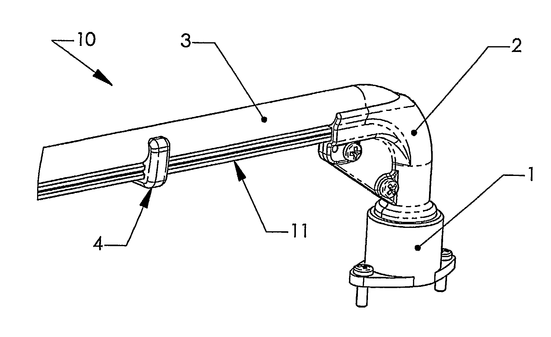
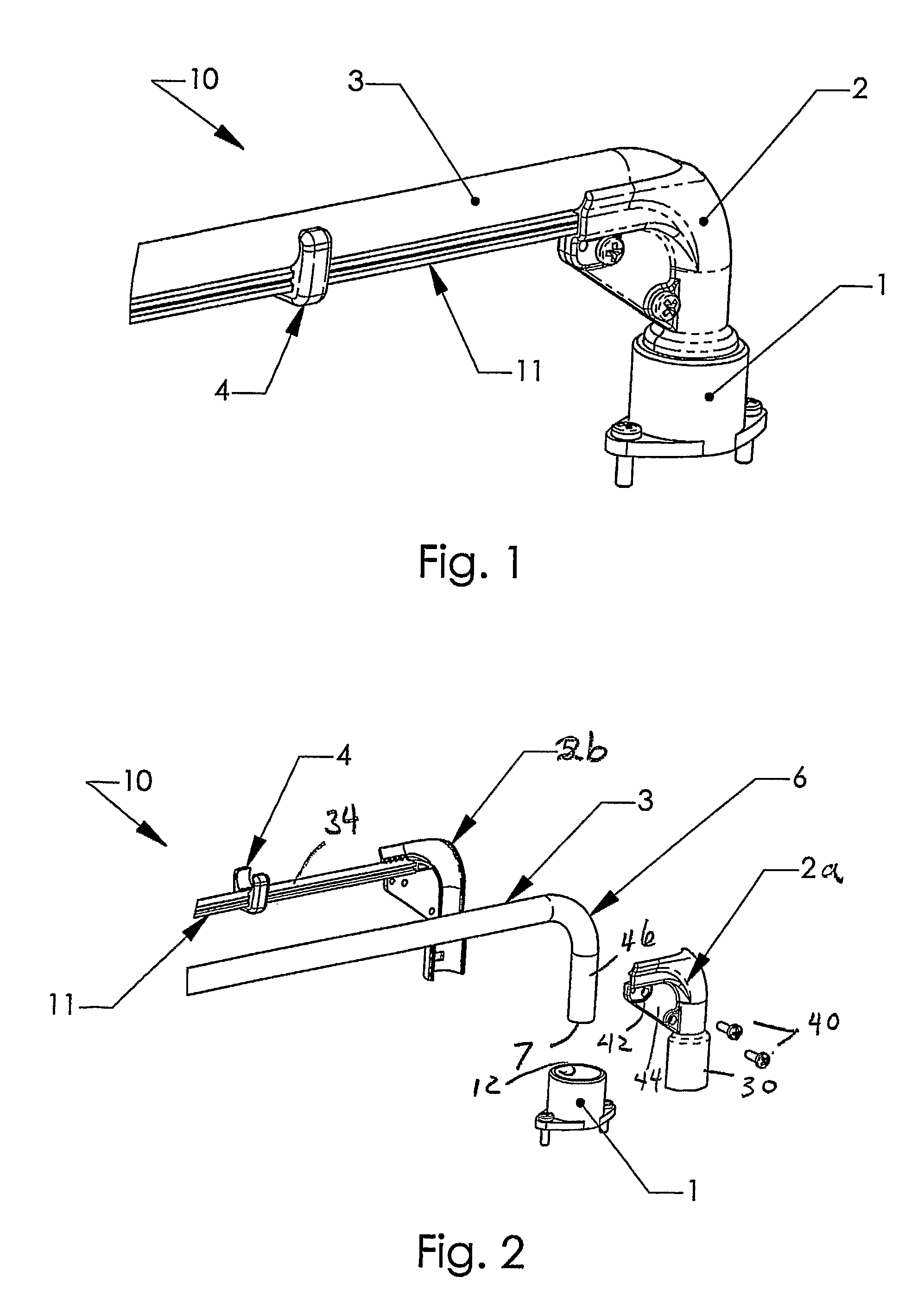
[0031]FIG. 1 is a perspective view of the illustrated embodiment 10 of the invention which is comprised of clamp 2 coupled to fiber optic cable 3 and mounted on a light engine 1. Light engine 1 includes a selectively chosen colored LED light source 14 best shown in the side cross sectional view of FIG. 5. Light engine 1 is positioned in the proximity of the end of fiber optic cable 3 by means of clamp 2, so that the LED light source 14 within engine 1 is optically coupled to cable 3 as shown in greater detail in connection with FIG. 5. Thus, it is to be understood that the physical configuration of engine 1 with respect to cable 3 can assume any form now known or later devised through which effective optical coupling into cable 3 is obtained. Further, although the light pipe or optic fiber has been described as a cable 3, it is also to be understood that any elongate means that is able to conduct light may be substituted, regardless of composition or size. For example, cable 3 in th...


PUM


Abstract

An improvement in LED lighting simulative of neon lighting comprises a light cable (3). A clamp (2) coupled to the cable (3) holds an end of the cable (3) in a predetermined bend, and an LED (14) is optically coupled to the cable (3). A support (11) is coupled to the clamp and includes a surface (34) adjacent to the cable (3) to reflect light incident on its surface, which is a diffuse reflector. A clip (4) retains the cable (3) on the support (11). The clamp (2) is at least partially opaque and shields an end of the cable (3) to simulate a neon tube. The LED light source (14) comprises a housing (12) to which the clamp (2) is coupled, and comprises an LED emitter and a reflector. The clamp (2) is mounted on a substrate (21) and at least one additional sign element mounted to the substrate, such as an LED backlit sign element.

Description

RELATED APPLICATIONS[0001]The present application is related to U.S. Provisional Patent Application Ser. No. 60 / 721,751, filed on Sep. 28, 2005, which is incorporated herein by reference and to which priority is claimed pursuant to 35 USC 119.BACKGROUND OF THE INVENTION[0002]1. Field of the Invention[0003]The invention relates to the field of light emitting diodes LED) and fiber optic lighting systems and in particular to a system which simulates neon lights or signage.[0004]2. Description of the Prior Art[0005]There have been many attempts to simulate neon with LEDs. Most of the solutions comprise a string of small LEDs closely spaced. The LEDs are encapsulated or covered with a diffusing material or lens. The resultant line of light generated by the LEDs appears to be continuous. One serious drawback of this type of device is that individual LEDs have widely varying life degradation curves. After a short period of time, the uniformity in output is no longer within a desirable rang...

Claims


Application Information

Patent Timeline
Patent Type & Authority Patents(United States)
IPC IPC(8): F21V17/00
CPCG02B6/0008G09F13/22G09F2013/1895
Inventor HOLDER, RONALD G.RHOADS, GREG
Owner SIGNIFY HLDG BV
Why Eureka
Try Eureka