Electrical connector

Active Publication Date: 2010-09-07
LOTES
View PDF4 Cites 33 Cited by
  • Summary
  • Abstract
  • Description
  • Claims
  • Application Information

AI Technical Summary

Benefits of technology

[0016]In comparison with prior art, according to the electrical connector of the present invention, since the elastic arms of the rear row of the electrical conductive terminals are located between the two adjacent elastic arms of the front row of the electrical conductive terminals. Thus, the adjacent front and rear rows of the electrical conductive terminals can be avoided from generating a short circuit or colliding with each other.
[0017]Further, the insulating body protrudes upwards to form at least two protective blocks that are located higher than the material-belt connecting portion. The electrical connector allows a chip to be mounted thereon. Therefore, when the chip is mounted on the electrical connector, the contacting portions of the electrical conductive terminals can be electrically connected to the chip. When the chip is pressed to a certain

Problems solved by technology

However, since the mainboard becomes smaller and smaller, the available space for the electrical connector on the mainboard is decreased accordingly.
However, such an electrical conductor has problems as follows.
As a result, short circuit or interference of signals will be generated.
Although this kind of electrical connector avoids the problem of short circuit in the previous electrical connector, it still brings about some problems as follows.
Further, the contact portion is located at the distal end of the elastic arm, so that the contact between the chip and the contacting portions may become poor when the chip is pressed

Method used


Image

  • Electrical connector
  • Electrical connector
  • Electrical connector

Examples


Embodiment Construction

[0023]In order to understand the objective, structure, characteristics, and effects of the present invention better, a description relating thereto will be made with reference to preferred embodiments thereof and the accompanying drawings. However, the drawings are illustrative only but not used to limit the present invention.

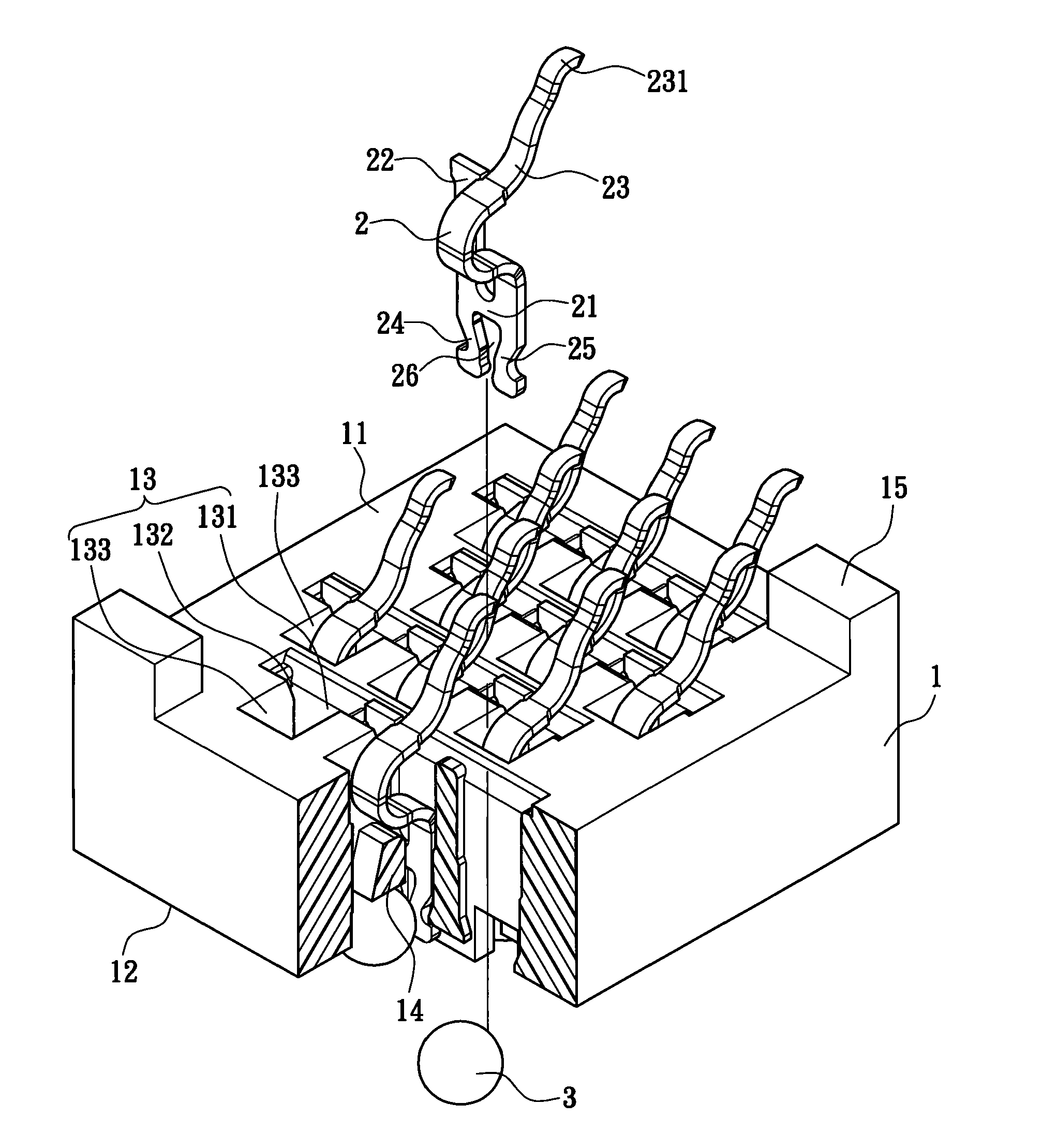
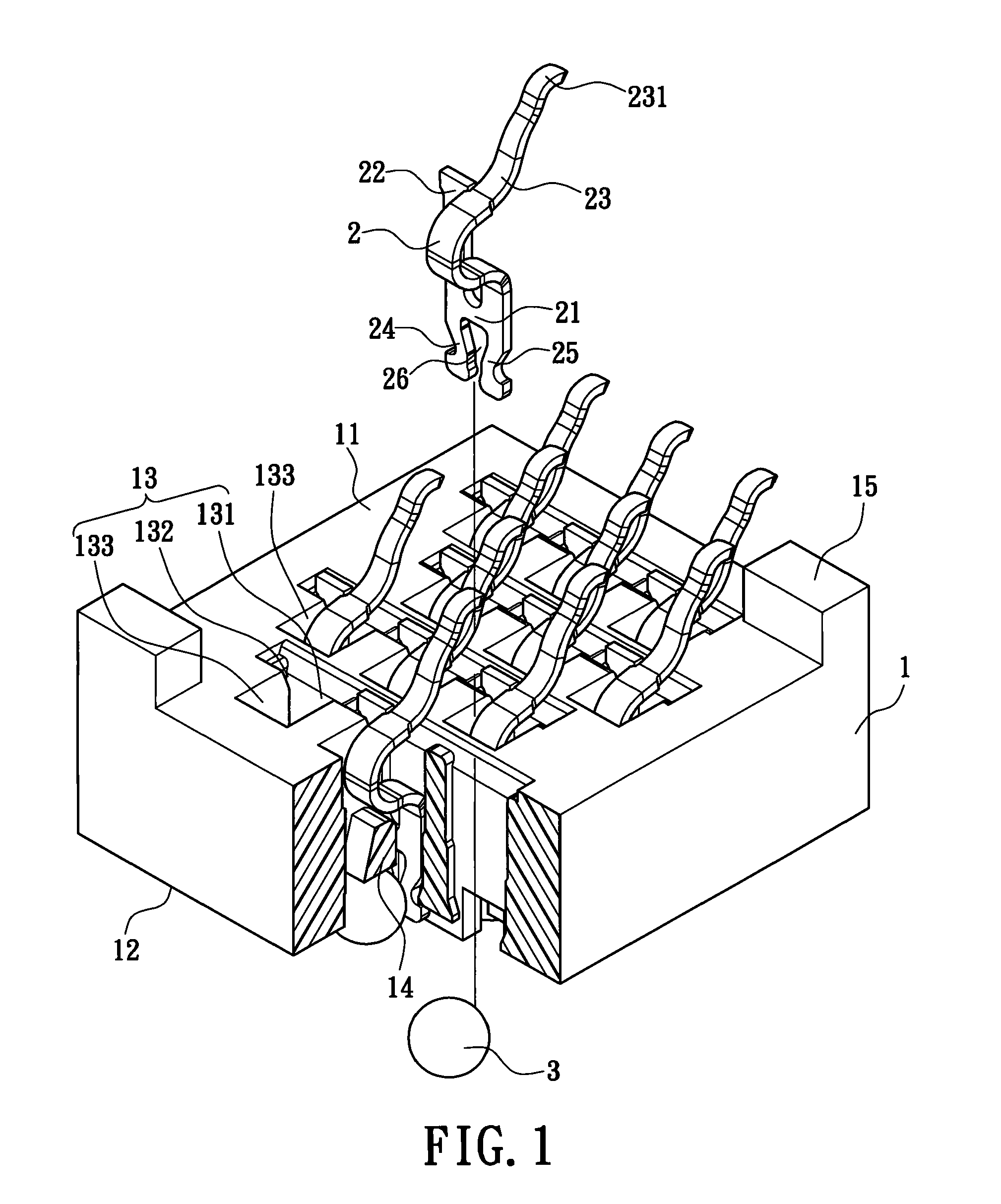
[0024]Please refer to FIG. 1. The electrical connector of the present invention includes an insulating body 1, a plurality of electrical conductive terminals 2 fixed in the insulating body 1, and a plurality of solder balls 3 received in the insulating body 1 to correspond to the electrical conductive terminals 2 respectively.

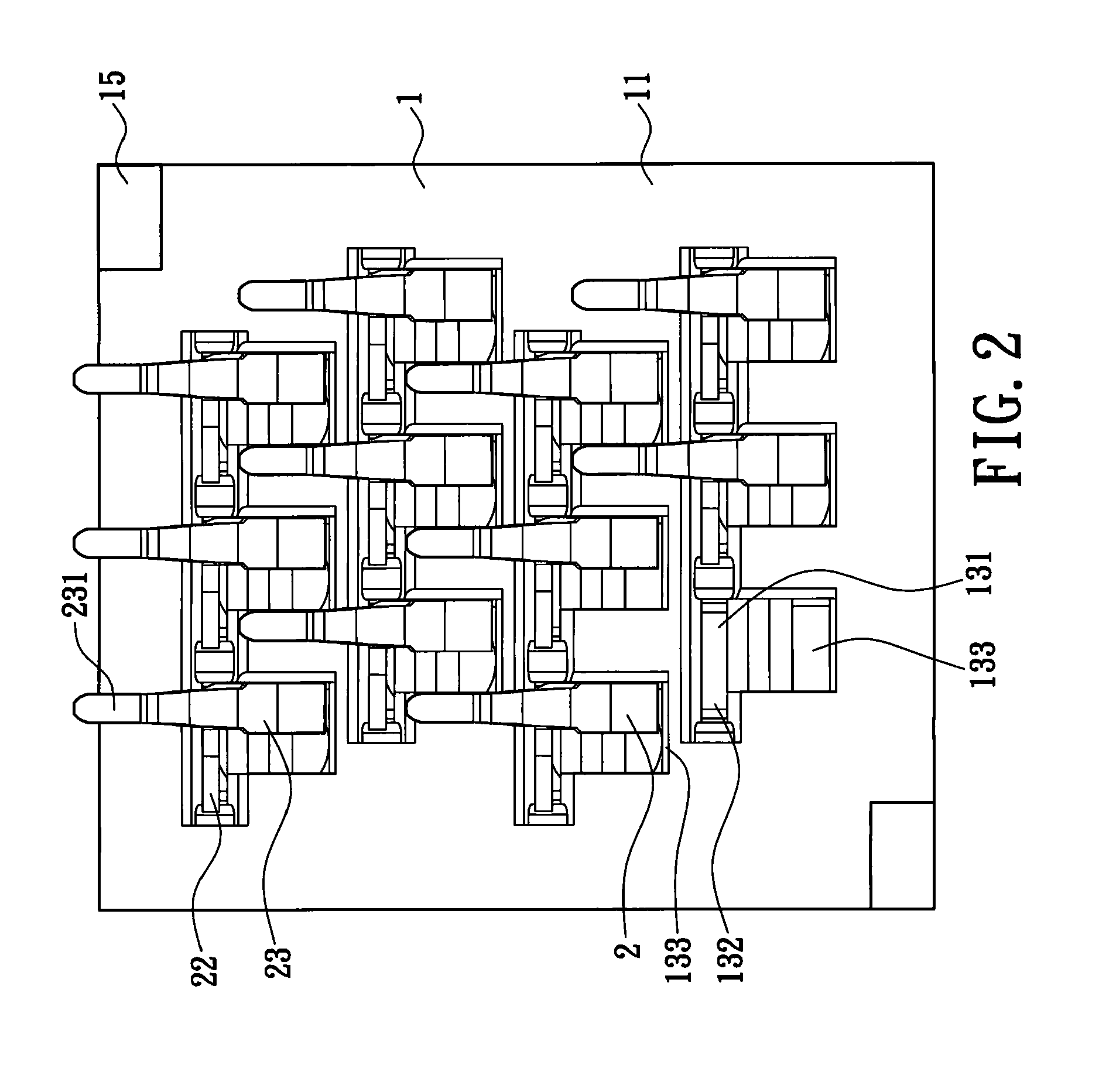
[0025]Please refer to FIGS. 1 to 3. The insulating body 1 includes an upper surface 11 and a lower surface 12 opposite to the upper surface 11. A plurality of accommodating troughs 13 is formed to penetrate the upper surface 11 and the lower surface 12. The accommodating troughs 13 are arranged in longitudinal and transverse rows on the in...


PUM


Abstract

An electrical connector includes an insulating body, which has plural front and rear rows of accommodating troughs for receiving electrical conductive terminals, and two protective blocks protruded upwardly. The accommodating portion has a first accommodating portion, a second accommodating portion extending laterally from the first accommodating portion, and a third accommodating portion extending rearwards from the first accommodating portion. A rear row of the second accommodating portions are located behind the adjacent front row of third accommodating portions. The electrical conductive terminal has a base, a material-belt connecting portion extending from one side of the base, an elastic arm extending from the elastic arm. The elastic arm is adjacent to and exceeds the material-belt connecting portion. The elastic arms of the rear row of the electrical conductive terminals are located between the two adjacent elastic arms of the front row of the electrical conductive terminals.

Description

BACKGROUND OF THE INVENTION[0001]1. Field of the Invention[0002]The present invention relates to an electrical connector and in particular to an electrical connector capable of preventing from generating a short circuit.[0003]2. Description of Prior Art[0004]With the advancement of the electronic industry, electrical connectors have become more and more important. Thus, it is an increasing need to improve the performance of electrical connectors. Under the same condition, in order to increase the transmission efficiency of the electrical connector, a common solution in this art is to increase the number of terminals. However, since the mainboard becomes smaller and smaller, the available space for the electrical connector on the mainboard is decreased accordingly. Thus, it is necessary for the terminals to be arranged more densely, so that various designs of the electrical connectors are developed.[0005]A conventional electrical connector at an earlier stage includes an insulating b...

Claims


Application Information

Patent Timeline
IPC IPC(8): H01F27/04
CPCH01R12/52H01R12/57H01R12/707H01R13/2442
Inventor JU, TED
Owner LOTES
Why Eureka
Try Eureka