Submerged loading system

a loading system and submerged technology, applied in the direction of passenger handling apparatus, buoys, transportation items, etc., can solve the problems of not economical to set up a large production system, complicated setup procedure for an arriving vessel, and high initial installation cost, so as to minimize the complexity and time consumed in connecting and disconnecting the vessel. , the effect of minimizing the cost of initial installation

Inactive Publication Date: 2010-09-14
SINGLE BUOY MOORINGS INC
View PDF70 Cites 15 Cited by
  • Summary
  • Abstract
  • Description
  • Claims
  • Application Information

AI Technical Summary

Benefits of technology

[0004]In accordance with one embodiment of the invention, an intermittent offshore transfer system is provided that transfers fluid between a vessel and a pipeline that has a stationary pipe end at the sea floor, wherein the vessel repeatedly sails away and returns, which minimizes the cost of initial installation of the system and that minimizes the complexity and time consumed in connecting and disconnecting the vessel. The only part that must be picked up and connected to by the arriving vessel, is the upper end(s) of one or more conduits that extend to the sea floor. Anchor chains or weight compensating back chains are not used, so they do not have to be initially installed, do not have to picked up, and do not have to be connected to the vessel.
[0006]In a preferred system, the conduit lower end includes a rigid reinforced hose section having a length of a plurality of meters, that connects to the stationary pipeline end and that extends a plurality of meters above the sea floor. The rigid hose section is preferably connected to the stationary pipeline end in a pivot pipe connection that allows the rigid hose section to pivot about two perpendicular axes. This reduces changes in hose bending as the DP vessel moves with waves and changes in winds.

Problems solved by technology

In this example, the undersea reservoir is small enough that it is not economical to set up a large production system, or this system has been set up as an early production system to produce hydrocarbons until a larger system is installed.
This results in a considerable cost to initially install the system, and the setup procedure for an arriving vessel is still complicated and time consuming.

Method used


Image

  • Submerged loading system
  • Submerged loading system
  • Submerged loading system

Examples


Embodiment Construction

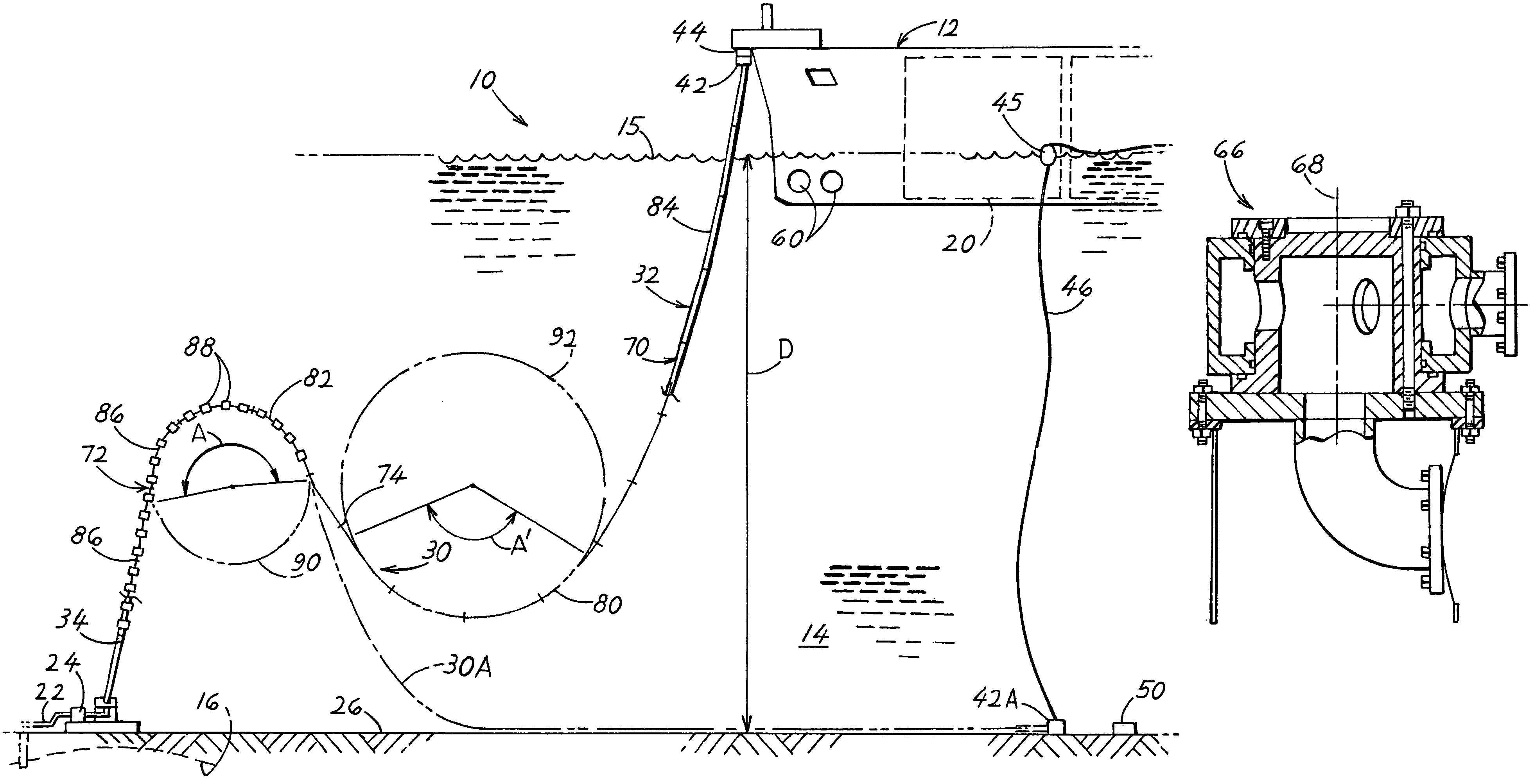
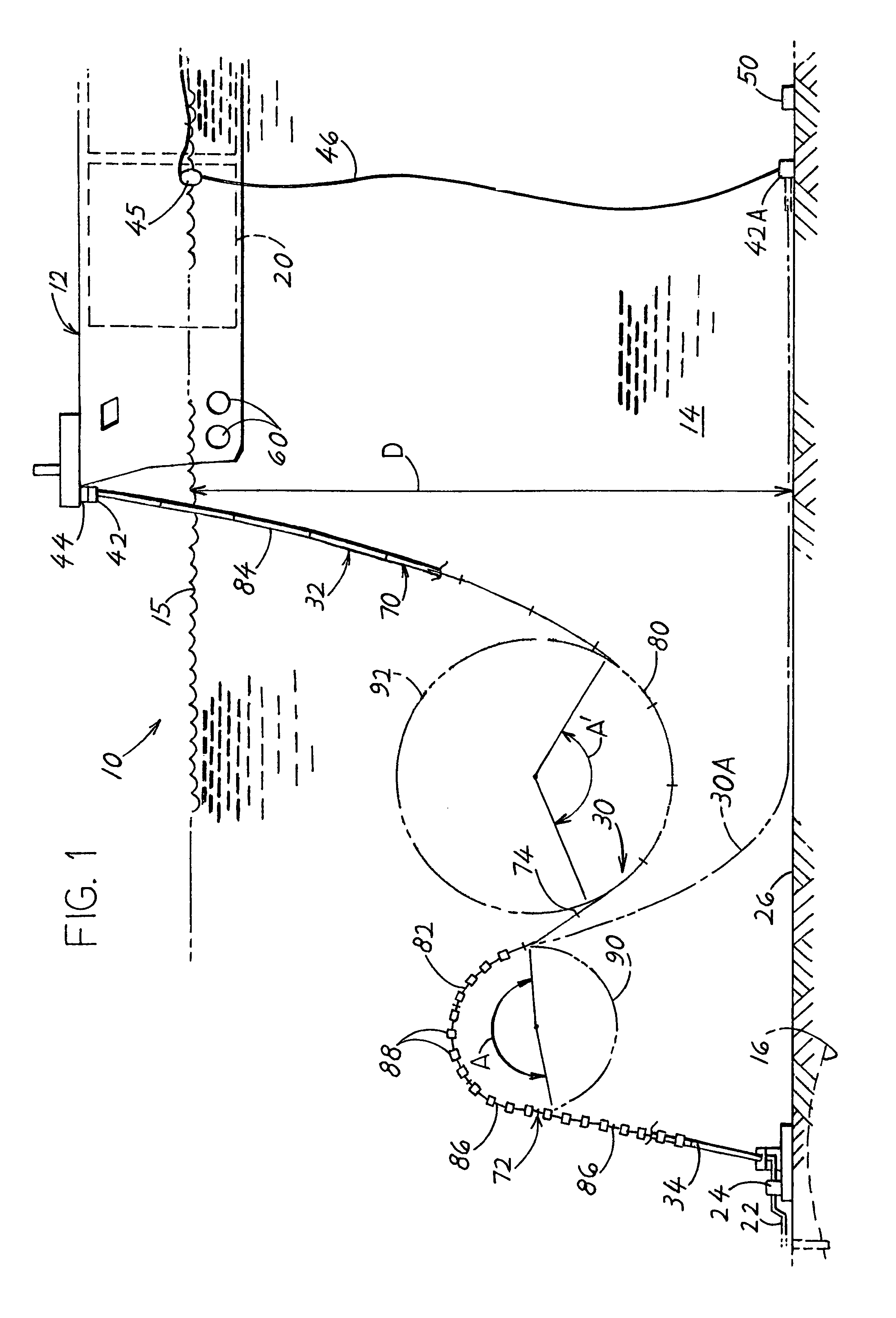
[0015]FIG. 1 shows a loading system 10 of one embodiment of the invention, that includes a DP (dynamic positioning) vessel 12 that lies at a location 14 in a sea of a depth D, and that produces hydrocarbons from an undersea reservoir 16 and stores them in tanks 20 in the vessel. When the tanks are full, the vessel sails away to a distant location where the hydrocarbons are unloaded (loaded to another pipe), and then the vessel sails back to the location 14. The hydrocarbons flow from the reservoir through a pipeline 22 that has a stationary pipe end 24 that lies substantially (within 5 meters) at the sea floor 26, and though a conduit 30 that connects to the vessel at the bow or middle of the vessel. The conduit includes a flexible hose 32 and a rigid reinforced hose 34. When not connected to the vessel, the conduit lies in the position 30A with a hose coupling 42A lying on the sea floor. When hydrocarbons are to transferred to the vessel, the hose coupling at 42 has been lifted and...


PUM


Abstract

An offshore system allows a vessel (12) to sail to a predetermined sea location (14), quickly set up a loading system and start the transfer of hydrocarbons to or from a pipeline (22), and then quickly disconnect and sail away. The vessel is a DP (dynamic positioning) vessel that does not require mooring or anchor lines, so the only apparatus to install is a conduit (30) that can be picked up by the vessel to extend between a stationary pipe end (24) that lies at the sea floor and the vessel. The conduit includes primarily a flexible hose (70) that extends in a sine wave with two loops (80, 82). The conduit includes a rigid reinforced hose section (34) that is pivotally connected to the sea floor. A chain (114) can be provided with a portion of the chain lying on the sea floor, to help the disconnected hose coupling (42D) remain at a stable position above the sea floor.

Description

CROSS-REFERENCE[0001]Applicant claims priority from U.S. Provisional Patent Application Ser. No. 60 / 760,069 filed Jan. 19, 2006.BACKGROUND OF THE INVENTION[0002]Intermittent offshore transfer systems are used to transfer fluids, especially hydrocarbons, between a vessel that repeatedly sails to and away from the system, and a pipeline that has a stationary pipe end lying at the sea floor. In one example, a transfer system is used in the production of hydrocarbons from an undersea reservoir, to transfer hydrocarbons passing from the reservoir along the pipeline up to the sea floor, up to the vessel. The vessel sails away to take the hydrocarbons to a distant location, offloads the hydrocarbons, and then returns for more. In this example, the undersea reservoir is small enough that it is not economical to set up a large production system, or this system has been set up as an early production system to produce hydrocarbons until a larger system is installed. In another example, a trans...

Claims


Application Information

Patent Timeline
Patent Type & Authority Patents(United States)
IPC IPC(8): E21B17/01E21B7/12B63B22/02
CPCB63B27/24E21B17/015Y10T137/402Y10T137/6906
Inventor VEDELD, STEINBALLERAUD, PIERREWILLE, HEIN
Owner SINGLE BUOY MOORINGS INC
Why Eureka
Try Eureka