
Stab and hinge-over pipeline and terminal assembly

a terminal assembly and pipeline technology, applied in the direction of fluid removal, pipe laying and repair, borehole/well accessories, etc., can solve the problems of the middle portion of the pipeline to buckle and drift from its base, damage the integrity of the pipeline, and the equipment associated with the end of the pipeline, and achieve the effect of reducing the number of pipelines

Active Publication Date: 2010-09-14
CHEVROU USA INC
View PDF22 Cites 12 Cited by
  • Summary
  • Abstract
  • Description
  • Claims
  • Application Information

AI Technical Summary

Benefits of technology

"The patent describes a system for securing an end portion of a pipeline to a subsea foundation. The system includes a subsea foundation with a receptacle, a base frame with a track, and a stab that is hingedly mounted to the base frame and stabbed into the receptacle to secure the base frame to the subsea foundation. The base frame can land on the subsea foundation or be supported by a foundation deck cantileverly mounted to the upper portion of the subsea foundation. The system also includes a sliding mechanism that moves along a track and is connected to a segment of the pipeline extending along the sea floor. The technical effects of the system include secure and stable attachment of the pipeline to the subsea foundation, and a sliding mechanism that allows for movement of the pipeline in response to forces from heating and cooling of the pipeline."

Problems solved by technology

When both of the pipeline ends are secured to fixed locations, such longitudinal expansion causes the middle portion of the pipeline to buckle and drift from its installed position, as well as exerting large forces on the structures at the ends of the pipeline.
Such buckling and drift can damage the integrity of the pipeline, as well as the equipment associated with the ends of the pipeline.
The expansion is even more significant, and creates larger forces, when the pipeline is extending along the sea floor for deep operations because the pressure and temperature of the surrounding deep water is more extreme than in shallower operations.
In previous assemblies, both ends of the pipeline have been secured to the sea floor, but this results in the problems discussed above.
Such assemblies alleviated much of the stress forces at the ends of the pipeline, but the end that is not secured tended to drift over a wide range due to the thermal expansion of the pipeline.
Such drift makes it difficult for workover operations and for connection of the end of the flowline with other subsea equipment.

Method used


Image

  • Stab and hinge-over pipeline and terminal assembly
  • Stab and hinge-over pipeline and terminal assembly
  • Stab and hinge-over pipeline and terminal assembly

Examples


Embodiment Construction

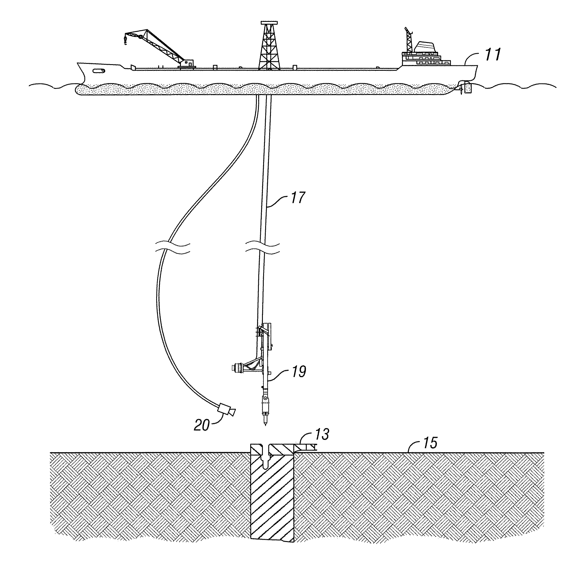
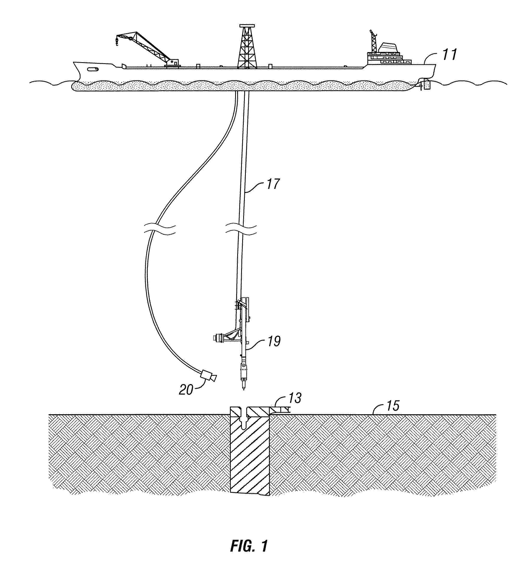
[0032]Referring to FIG. 1, an installation vessel 11 sails on the sea surface at a predetermined location above a suction pile or foundation pile 13 attached to the sea floor 15. Foundation pile 13 is preferably embedded into sea floor 15 with an upper portion extending above sea floor 15. Foundation pile 13 preferably extends a predetermined distance into sea floor 15, with a majority of foundation pile 13 being embedded under the mudline, or upper surface, of sea floor 15. By way of example, a typical foundation pile 13 has a length of about seventy-three (73) feet and a diameter of about twelve (12) feet, with at least fifty (50) feet of the length of foundation pile 13 being embedded into sea floor 15. While vessel 11 is illustrated as a “J-Lay” vessel, vessel 11 can also be an “S-lay” vessel or a “REEL” vessel.

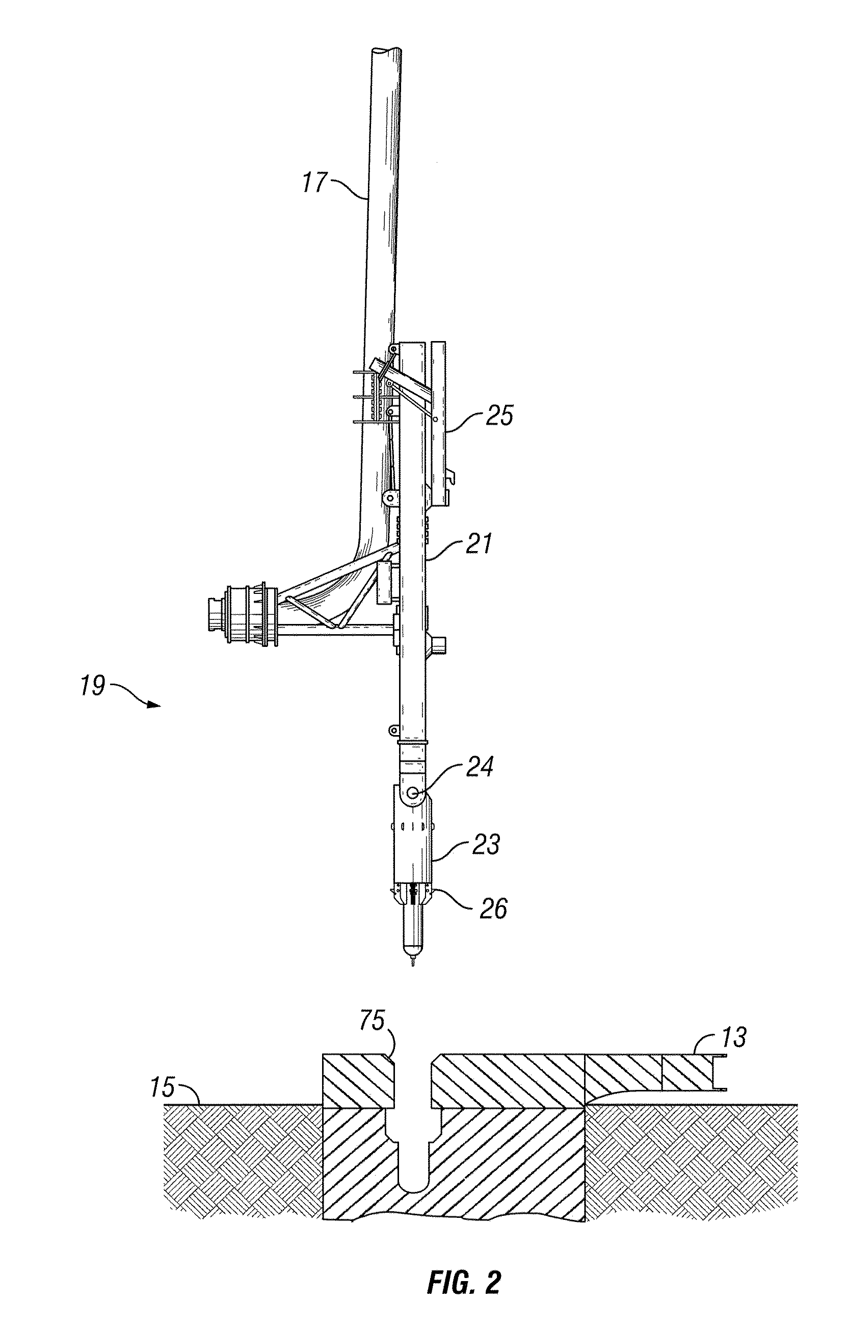
[0033]A stab and hinge-over pipeline end terminal (PLET) 19 is connected to an end portion of a string of flowline or pipeline 17 to be laid along sea floor 15. As is rea...


PUM


Abstract

A subsea system for securing an end portion of a pipeline includes a subsea foundation. The foundation has a lower portion located below the sea floor and an upper portion extending above the sea floor. The subsea foundation has a receptacle formed in the upper portion. The system includes a base frame that lands on the subsea foundation. The base frame has a track formed therein. A stab is hingedly mounted to the base frame. The stab stabs into the receptacle to secure the base frame to the subsea foundation. A sliding mechanism is carried by the base frame and moves along the track. The sliding mechanism is connected to a segment of the pipeline extending along the sea floor. A terminal assembly for an end portion of a pipeline and a method for securing an end portion of a pipeline are also included herein.

Description

CROSS-REFERENCE TO RELATED APPLICATIONS[0001]This application claims the benefit of U.S. Provisional Application No. 60 / 938,530, filed May 17, 2007.BACKGROUND OF THE INVENTION[0002]1. Field of the Invention[0003]This invention relates in general to the conveyance of hydrocarbons from a subsea well or wells, and in particular to an apparatus and assembly, and methods associated therewith, for a pipeline end terminal and foundation assembly for a subsea pipeline.[0004]2. Background of the Invention[0005]When conveying hydrocarbons from a subsea well, the hydrocarbons are often communicated through a flowline extending along the surface of the sea floor. The flowline extends from a single subsea wellhead, from subsea processing equipment, or from a subsea collection manifold.[0006]The flowline or pipeline often expands and contracts due to the heat emitted from the flow of hot hydrocarbons passing through the flowline. The flowline contracts when the flow of the hydrocarbons is stopped...

Claims


Application Information

Patent Timeline
Patent Type & Authority Patents(United States)
IPC IPC(8): F16L1/12
CPCE21B41/04E21B43/013F16L1/16F16L1/26
Inventor DELACK, KRISTEN
Owner CHEVROU USA INC
Features
  • Generate Ideas
  • Intellectual Property
  • Life Sciences
  • Materials
  • Tech Scout
  • Unparalleled Data Quality
  • Higher Quality Content
  • 60% Fewer Hallucinations
Learn More