Apparent incoherence method

a technology of incoherence factor and apparent incoherence factor, which is applied in the direction of electrical apparatus, wave amplification devices, laser details, etc., can solve the problems loss of information, and degrade quality, so as to suppress the measured intensity variation in spatial pattern spatial patterns, minimize the apparent incoherence factor, and suppress the effect of laser speckle and environmental induced scintillation effects

Active Publication Date: 2010-09-14
THE GOVERNMENT OF THE UNITED STATES AS REPSESENTED BY THE SEC OF THE AIR FORCE +1
View PDF3 Cites 14 Cited by
  • Summary
  • Abstract
  • Description
  • Claims
  • Application Information

AI Technical Summary

Benefits of technology

[0013]The present invention discloses a method and system whereby a narrow linewidth coherent laser source when transmitted as a plurality of output signals and subsequently detected at a distance appears to produce the uniform illumination characteristics of an incoherent source, thereby suppressing laser speckle and environmentally induced scintillation effects. The output of a master oscillator source, either cw or pulsed, is split into...

Problems solved by technology

Speckle and scintillation have been limiting factors in information transfer with coherent light sources since the advent of the laser.
In an imaging system the mottled intensity pattern overlays the actual image and degrades quality.
A variation in power at the detector can result in a loss of information.
The drawback to this technology is the fact that a broad bandwidth source is required, an unattractive feature for FSO.
The arrangement does not address speckle issues and does not apply to FSO and imaging systems which require large bandwidth information capture.
The mechanical nature of the solutions rendered these methods unsuitable for many FSO implementations.
However, Tsikos fails to discuss temporal phase modulation by use of myriad ...

Method used


Image

  • Apparent incoherence method
  • Apparent incoherence method
  • Apparent incoherence method

Examples


Embodiment Construction

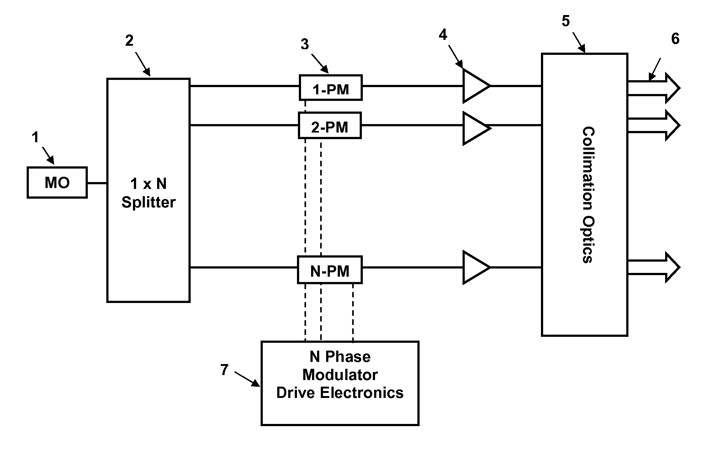
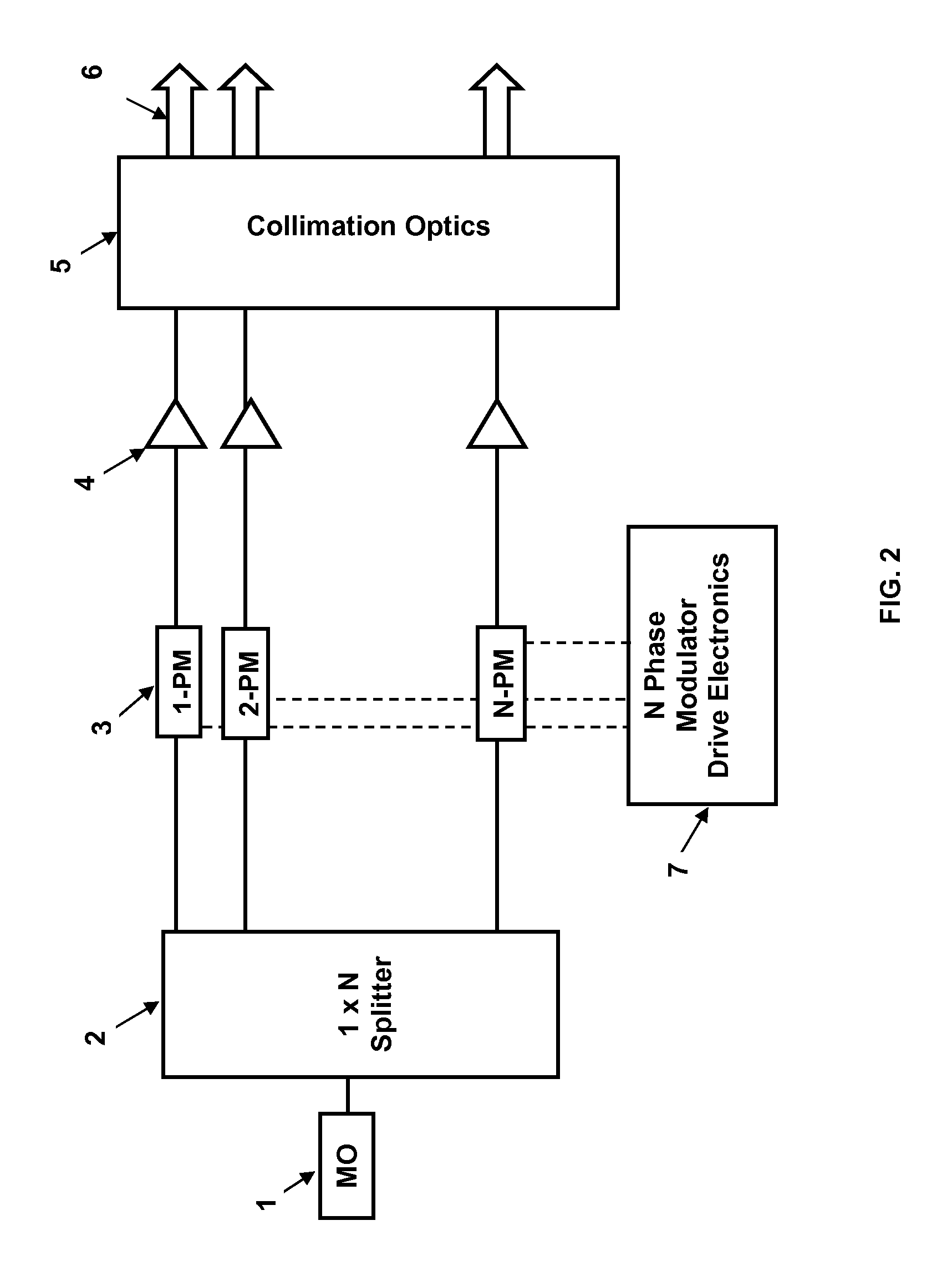
[0017]A novel method is described below that enables even narrow linewidth multiple coherent emitters to appear to produce the uniform illumination characteristic of an incoherent source. Additional significant applications for these techniques are the suppression of laser speckle and environmentally induced scintillation effects. Combining any two coherent electric fields will result in interference effects that spatially redistribute intensity, producing relatively bright and dark areas, commonly called fringes. These fringes are a direct result of the phase difference between the combined fields, giving either constructive or destructive interference. For coherent illumination, the phase relationships between fields are well-defined, producing easily-detected fringes that can be undesirable in applications requiring uniform illumination. The locations of the dark and bright fringes generally shift in an arbitrary manner unless complex systems are utilized to stabilize the path le...


PUM


Abstract

A method and system whereby a narrow linewidth coherent laser source when transmitted as a plurality of output signals and subsequently detected at a distance appears to produce the uniform illumination characteristics of an incoherent source thereby suppressing laser speckle and environmentally induced scintillation effects. A master oscillator source is split into N signals, each of which is independently phase modulated by frequencies designed to minimize a derived apparent incoherence factor. The signals are then either directed to an object to be illuminated so that they overlap at the object or first recombined and directed to the object.

Description

STATEMENT OF GOVERNMENT INTEREST[0001]The conditions under which this invention was made are such as to entitle the Government of the United States under paragraph I(a) of Executive Order 10096, as represented by the Secretary of the Air Force, to the entire right, title and interest therein, including foreign rights.BACKGROUND OF THE INVENTION[0002]The present invention generally relates to an improved method and apparatus for coherent optical information processing, and in particular to the reduction and elimination of the measured intensity variations in spatial patterns due to laser speckle and / or propagating-media-induced spatial or temporal phase shifts. The invention has application for coherent optical imaging, free space optical communications (FSO), and anywhere an incoherent, narrow bandwidth, optical source is needed[0003]Speckle and scintillation have been limiting factors in information transfer with coherent light sources since the advent of the laser. Speckle is the ...

Claims


Application Information

Patent Timeline
IPC IPC(8): H01S3/00
CPCH04B10/1121
Inventor SHAY, THOMAS M.ROBIN, CRAIG A.GAVRIELIDES, ATHANASIOSSPRING, JUSTIN
Owner THE GOVERNMENT OF THE UNITED STATES AS REPSESENTED BY THE SEC OF THE AIR FORCE
Why Eureka
Try Eureka