Supercharge Your Innovation With Domain-Expert AI Agents!

Seismic damper

a damper and damping technology, applied in the field of seismic dampers, can solve the problem of unsatisfactory thermal stress between the first end of the plate, and achieve the effect of reducing the risk of shock and vibration

Inactive Publication Date: 2010-09-21
SU YUNG FENG
View PDF8 Cites 11 Cited by
  • Summary
  • Abstract
  • Description
  • Claims
  • Application Information

AI Technical Summary

Benefits of technology

"The present invention provides a seismic damper that can allow relative movement of structures in a first direction due to seismic forces. The seismic damper includes upper and lower brackets, and a link mechanism. The link mechanism includes a support link, first and second pivot joints, and a third pivot joint. The link mechanism is designed to allow for smooth movement of the structures during a seismic event. The upper bracket is secured to the supported structure and has an upper hole through which the support link passes. The lower bracket is secured to the supporting structure and has lower and intermediate holes through which the support link passes. The link mechanism is designed to allow for smooth movement of the structures during a seismic event."

Problems solved by technology

The aforementioned conventional seismic damper is disadvantageous in that, since the first ends of the plates 12 are connected fixedly to the upper bracket 13 through welding, undesirable thermal stress is produced between the first ends of the plates 12 and the upper bracket 13.

Method used


Image

  • Seismic damper
  • Seismic damper
  • Seismic damper

Examples


Embodiment Construction

[0020]Before the present invention is described in greater detail, it should be noted that like elements are denoted by the same reference numerals throughout the disclosure.

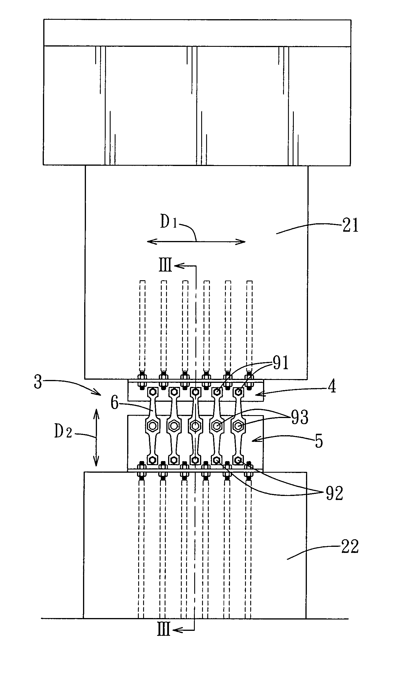
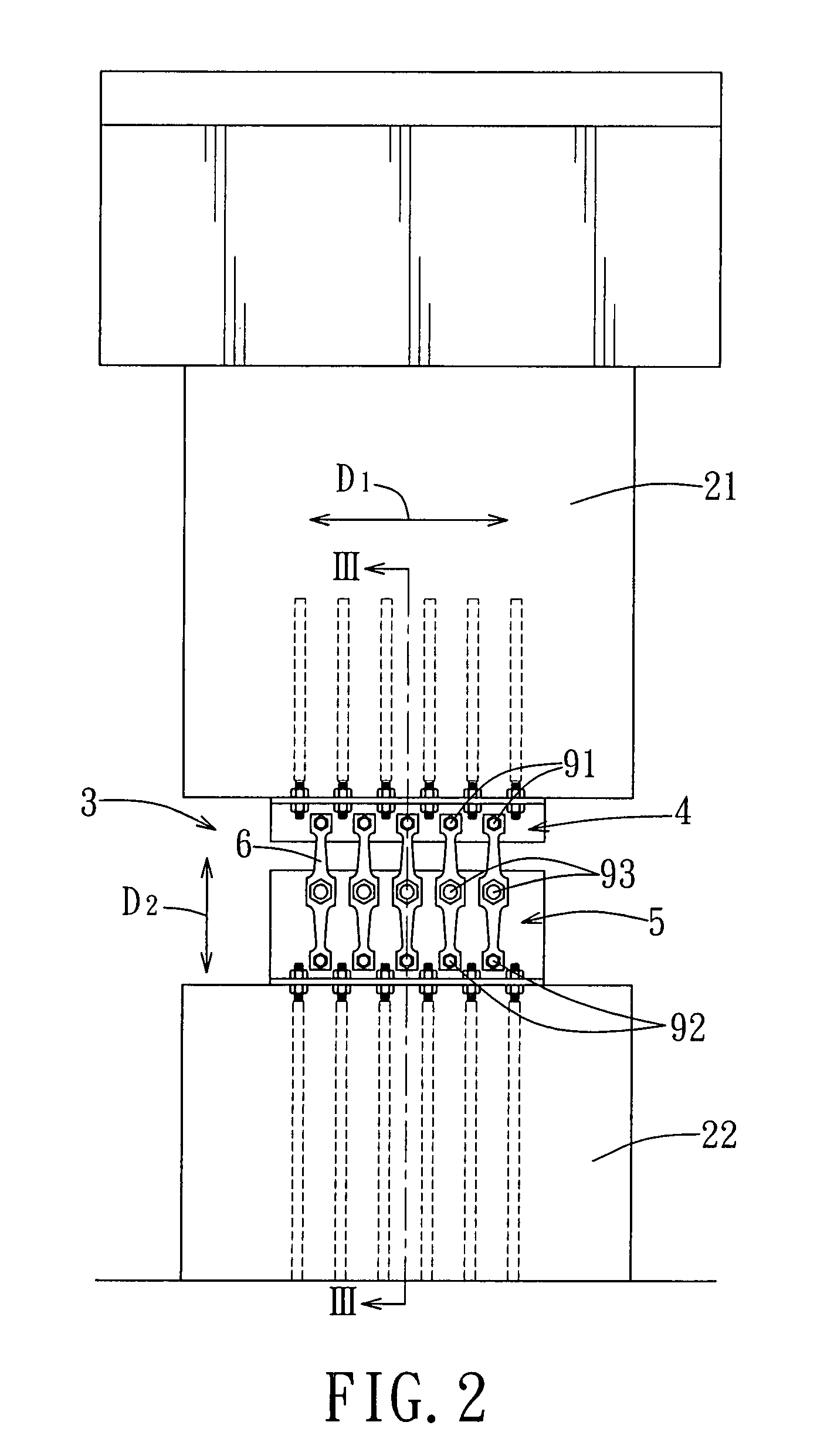
[0021]Referring to FIG. 2, the first preferred embodiment of a seismic damper 3 according to this invention is shown to include upper and lower brackets 4, 5, and a link mechanism 6.

[0022]The seismic damper 3 of this embodiment permits relative movement between supported and supporting structures 21, 22 in a first direction, as indicated by arrow (D1), due to seismic forces, in a manner that will be described hereinafter.

[0023]Each of the supported and supporting structures 21, 22 may be a wall, a beam, a column, or a bridge.

[0024]With further reference to FIG. 3, the upper bracket 4 has a generally T-shaped cross-section across a plane transverse to the first direction (D1), and includes horizontal and vertical bracket members 41, 42. The horizontal bracket member 41 of the upper bracket 4 is secured to the sup...


PUM


Abstract

A seismic damper includes upper and lower brackets, and a link mechanism. The upper bracket is formed with an upper hole. The lower bracket is formed with lower and intermediate holes. The link mechanism includes a support link, and first, second, and third pivot joints. The support link has first and second ends, each of which is formed with a through-hole, and an intermediate portion, which is formed with a through-hole. The first pivot joint extends through the upper hole in the upper bracket and the through-hole in the first end of the support link. The second pivot joint extends through the lower hole in the lower bracket and the through-hole in the second end of the support link. The third pivot joint extends through the intermediate hole in the lower bracket and the through-hole in the intermediate portion of the support link.

Description

CROSS-REFERENCE TO RELATED APPLICATION[0001]This application claims priority of Taiwanese application no. 096117631, filed on May 17, 2007.BACKGROUND OF THE INVENTION[0002]1. Field of the Invention[0003]This invention relates to a seismic damper, more particularly to a seismic damper that is capable of sustaining relatively strong seismic forces.[0004]2. Description of the Related Art[0005]FIG. 1 illustrates a conventional seismic damper for permitting relative movement of supported and supporting structures (not shown) in a first direction, as indicated by arrow (A), due to seismic forces. The conventional seismic damper includes upper and lower brackets 13, 14, and a link mechanism 1. Each of the upper and lower brackets 13, 14 is secured to a respective one of the supported and supporting structures. The link mechanism 1 includes a plurality of plates 12. Each of the plates 12 has a first end connected fixedly to the upper bracket 13, and a second end connected pivotably to the l...

Claims


Application Information

Patent Timeline
Patent Type & Authority Patents(United States)
IPC IPC(8): E04B1/98
CPCE04H9/02E04H9/028E04H9/021E04H9/0237
Inventor SU, YUNG-FENG
Owner SU YUNG FENG
Features
  • R&D
  • Intellectual Property
  • Life Sciences
  • Materials
  • Tech Scout
  • Unparalleled Data Quality
  • Higher Quality Content
  • 60% Fewer Hallucinations
Learn More