Loading rack

a technology of loading racks and racks, applied in the field of loading racks, to achieve the effects of reducing the rattling of the leg in a standing position, stable state, and reducing the error of fittings

Inactive Publication Date: 2010-09-21
NANKAI INDS
View PDF7 Cites 2 Cited by
  • Summary
  • Abstract
  • Description
  • Claims
  • Application Information

AI Technical Summary

Benefits of technology

[0014]Also, the present invention may further have a pin which projects upwardly at a middle of a left-right direction of each leg; and a fitting hole opened on the table body, in which the pin is inserted when the leg is in a standing position. With that, rattling of the leg in a standing position is decreased by reducing a fitting error between the pin and the fitting hole so that it is possible to achieve the more stable state.
[0015]The loading rack of said present invention may further have a claw bearing member attached to a lateral portion of the table body in which a fork of a forklift truck is inserted, wherein the claw bearing member is attached at a location so that the rack is able to be balanced when the fork is inserted in the claw bearing member. Even if the gravity point of the loading rack and the baggage on it is put to the front of the fork when the fork is inserted into the claw being member and the loading rack is lifted, it is possible to prevent them from falling down in front since the rack is supported by two points, which are on a front end of the fork which extends in front from the claw being part and the claw bearing part. Also, it is possible to load and unload the loading rack with baggage on it by the fork at the predetermined position and in a stable state wherein the front and back are not shaken since the claw bearing member is attached to a position in which the rack is able to be balanced when the fork is inserted into the claw bearing member. Consequently, it is possible to prevent baggage on the loading rack from losing balance and slipping down during loading and unloading.
[0016]It is preferable to make it possible to choose a state of the claw member from two states, of which one is a standing state wherein the claw bearing member is in a first angular relationship at a right angle to the table body and the other state is a closed state wherein the claw bearing member is in a different angular relationship parallel to the table body. With this construction, by folding the claw bearing member when the leg is in the standing position to put baggage both above and below the table body, it is possible to prevent the space for storing baggage under the table from being reduced caused by the claw bearing member which is in a standing state and the baggage from getting broken by contacting the claw bearing member.
[0017]In this case, it is preferable to have an engaging member, which fixes the state, as the claw bearing member is in a closed state wherein it is parallel to the table body. With this construction, it is possible to maintain the closing state without fail and prevent the claw bearing member from hanging downwardly by itself as caused by vibration during movement of the vehicle.
[0018]Moreover, it is preferable to have a holding assembly, which temporarily holds the standing state of the claw bearing member wherein the claw bearing member is at right angle to the table body. With this, it is possible to eliminate the shakiness, such as wobbling, of the claw bearing member when it is in the standing state, so that the fork is inserted to the claw bearing member easily.
[0019]With the present invention, despite a simple structure, it is possible to achieve an enhancement of the strength of hinged legs for the loading rack and facilitate opening and closing of the legs. The legs may be held in a standing state against a large moment by ensuring the enough length of the insertion parts extends into the supporting holes in the vertical direction.

Problems solved by technology

Also, almost all weight of the table body itself and the luggage loaded on the table body weighs on a part of the leg except the insertion part.

Method used


Image

  • Loading rack
  • Loading rack
  • Loading rack

Examples


Embodiment Construction

[0027]With reference to the attached drawings, the present invention will hereinafter be described by way of an embodiment thereof. However, a structure of a hinge part, which is a feature of this invention, is focused on because the basic composition and advantages of the loading rack are otherwise the same as in the prior art.

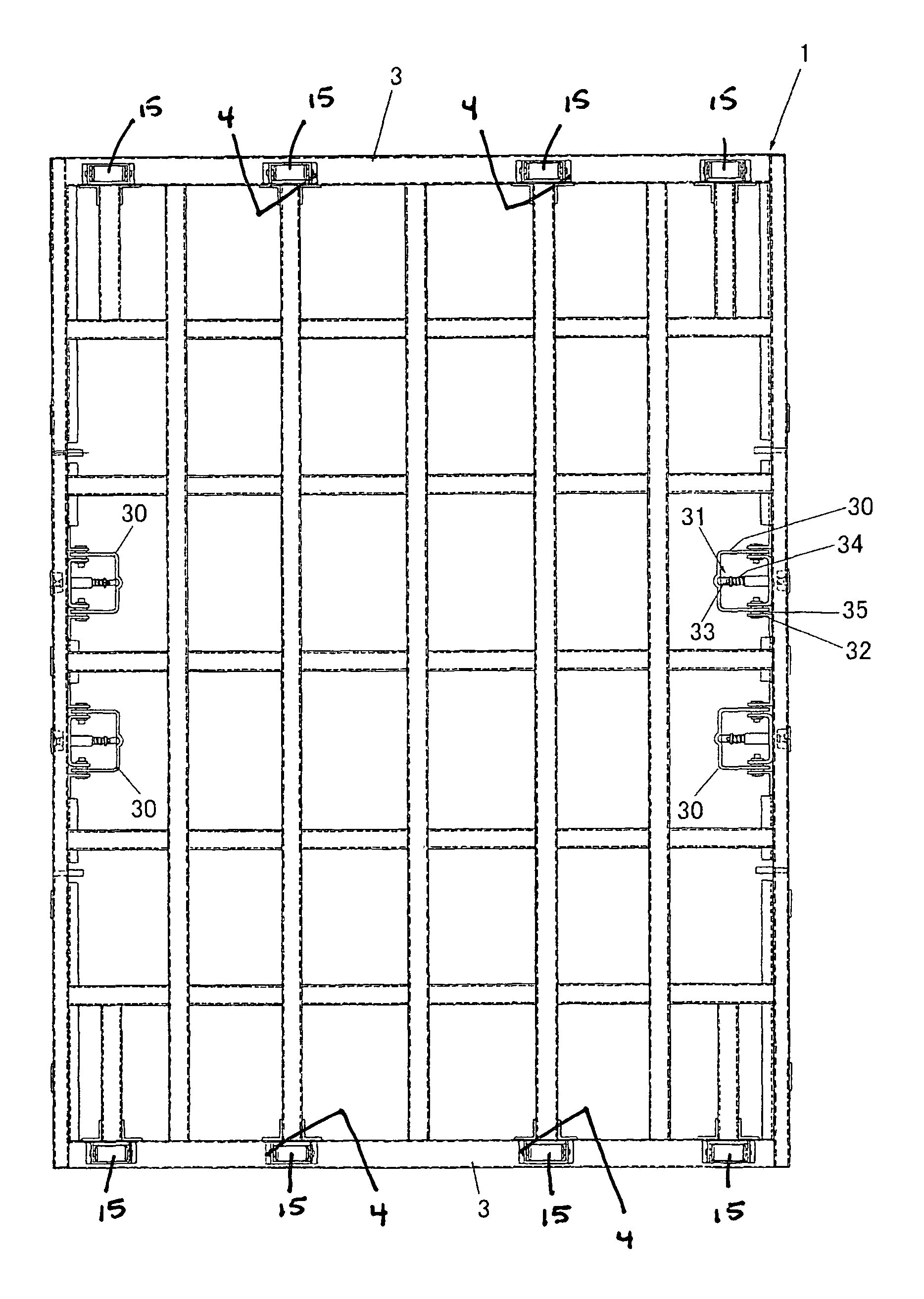
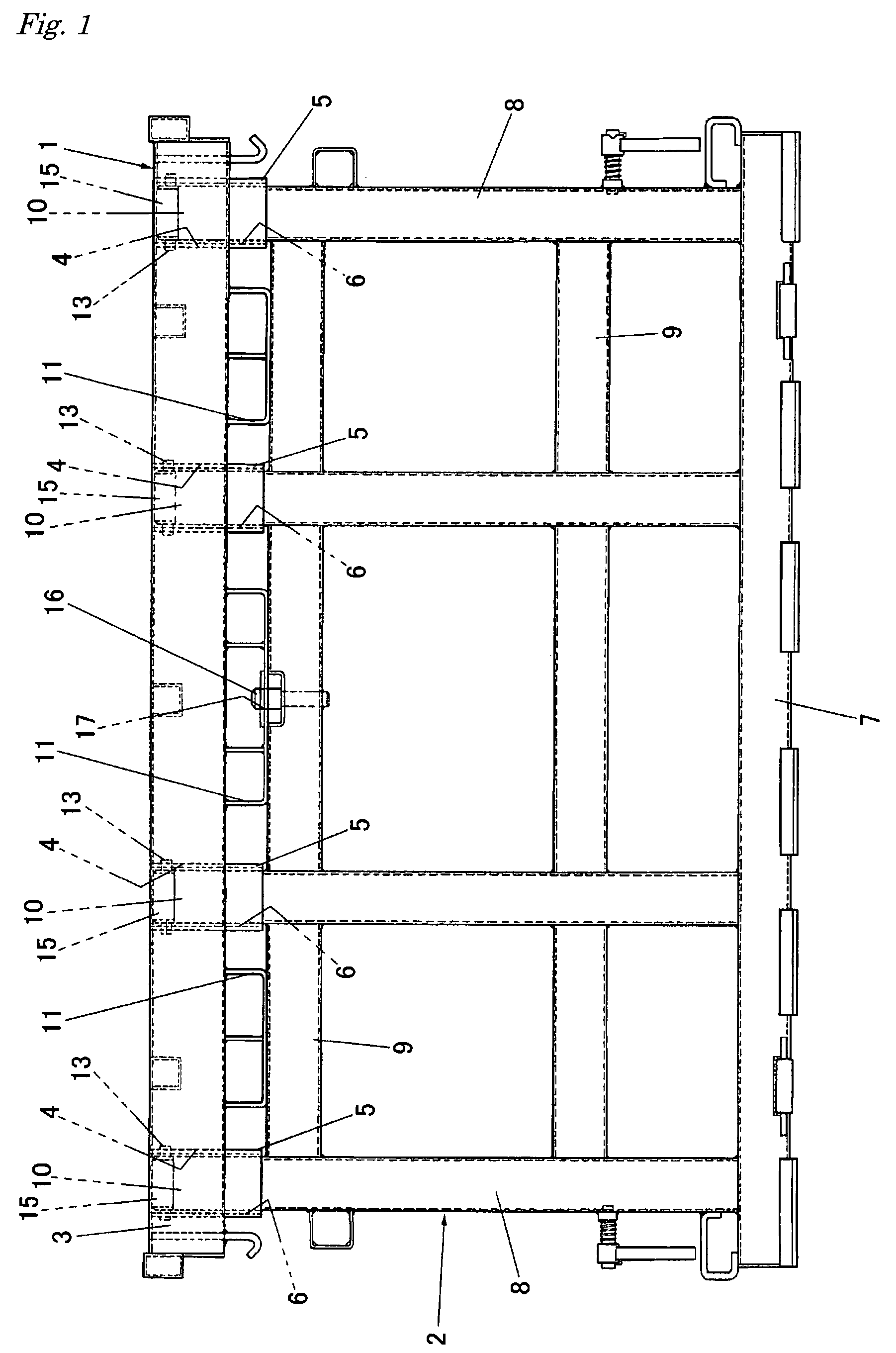
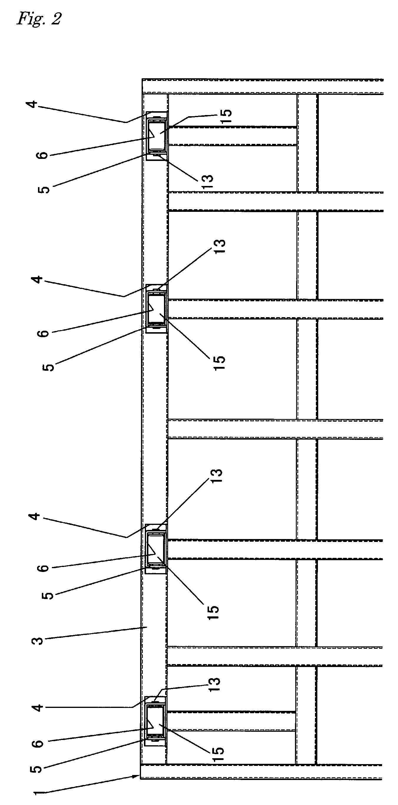
[0028]FIGS. 1 to 6 illustrate a loading rack of the present invention. The loading rack has a table body 1, which has an oblong shape in plan view and is formed in a manner wherein square-shaped pipe components are assembled in a lattice pattern, and a pair of legs 2, are foldably attached, one each, to anterior / front and posterior / rear side parts of the table body 1. The leg 2 is capable of being placed in a vertical orientation (being able to be set up) or foldable in a state wherein the bottom surface of the table body 1 is raised by the fork of a forklift car. The state wherein the leg 2 is set up is referred as a “standing position” in the embodiment.

[00...


PUM


Abstract

A loading rack with an oblong table body having a lateral extent and posterior and anterior ends and a pair of legs attached closably/foldably to posterior and anterior side parts of the body. The loading rack further has a plurality of leg holders which are attached at laterally spaced locations to the posterior and anterior side of the table body and a supporting hole which opens downwardly on each leg holder. Multiple insertion parts on an upper part of each of the legs can be inserted one each into the supporting holes. Each leg is held and fixed in a vertically standing position by peripheral walls surrounding the supporting holes as insertion parts are inserted into the supporting holes and the table body is loaded on the leg.

Description

BACKGROUND OF THE INVENTION[0001]1. Field of the Invention[0002]This invention relates to the field of loading racks, which divide out the loading space of containers, box-shaped rear bodies of trucks, and the like vertically (upwardly and downwardly) so that the loading space is used efficiently.[0003]2. Prior Art[0004]As this kind of conventional loading racks, for example, racks written in following Patent Application Gazettes are known:[0005]Japanese published unexamined application 2005-153815; and[0006]Japanese published unexamined application 2005-041299.[0007]Both of them have two legs, which have half the height of the box-shaped rear body of trucks and are fixed foldably to posterior and anterior side parts of an oblong table body, which vertically divides (partitions) the inner space of the rear box. Each of the legs has two poles, a horizontal frame of at the lower end, strengthening frames at vertical two places. A hinge of the leg is structured in a manner wherein a ta...

Claims


Application Information

Patent Timeline
Patent Type & Authority Patents(United States)
IPC IPC(8): B65D19/00
CPCB65D90/14B65D88/129B60P1/64B60P3/40B62D33/02
Inventor KASHIHARA, TERUO
Owner NANKAI INDS
Why Eureka
Try Eureka