Cantilevered nozzle with crowned flange to improve outer band low cycle fatigue

a technology of crowned flanges and cantilevered nozzles, which is applied in the direction of machines/engines, machine supports, liquid fuel engines, etc., can solve the problems of reducing the durability of the outer band and the turbine vane segment, and compromising the durability of the multiple vane segments

Active Publication Date: 2010-09-21
GENERAL ELECTRIC CO
View PDF9 Cites 18 Cited by
  • Summary
  • Abstract
  • Description
  • Claims
  • Application Information

AI Technical Summary

Problems solved by technology

However, the longer chord length of the outer band and mounting structure compromises the durability of the multiple vane segment nozzles.
The increased thermal stress may reduce the durability of an outer band and the turbine vane segment.

Method used


Image

  • Cantilevered nozzle with crowned flange to improve outer band low cycle fatigue
  • Cantilevered nozzle with crowned flange to improve outer band low cycle fatigue
  • Cantilevered nozzle with crowned flange to improve outer band low cycle fatigue

Examples


Embodiment Construction

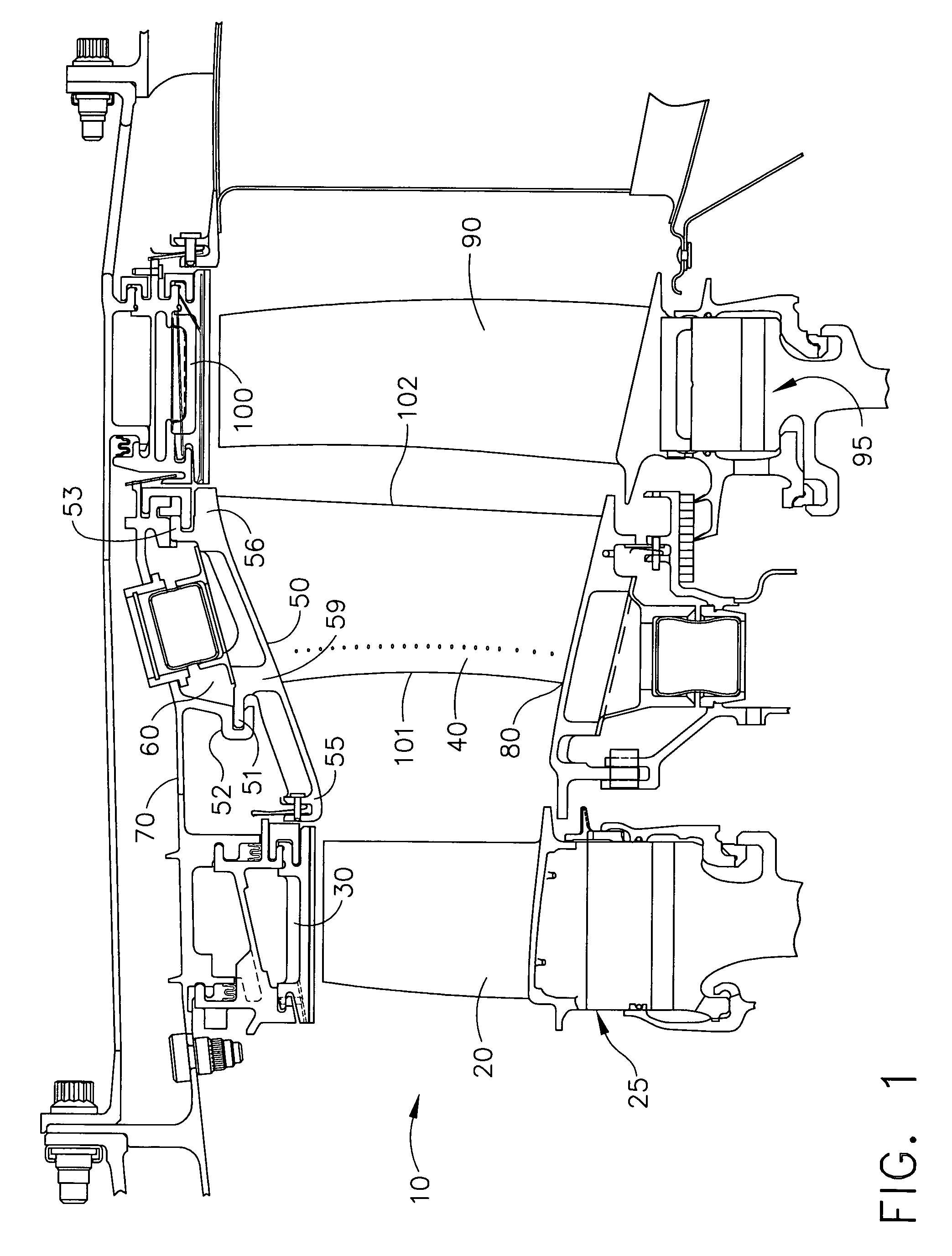
[0016]Referring to the drawings wherein identical reference numerals denote the same elements throughout the various views, FIG. 1 a portion of turbine stage 10 comprising a Stage 1 turbine rotor 25, a Stage 2 turbine rotor 95 and a Stage 2 turbine nozzle 40 located in between. Turbine blades 20 and 90 are circumferentially arranged around the rim of the Stage 1 and Stage 2 turbine rotors respectively.

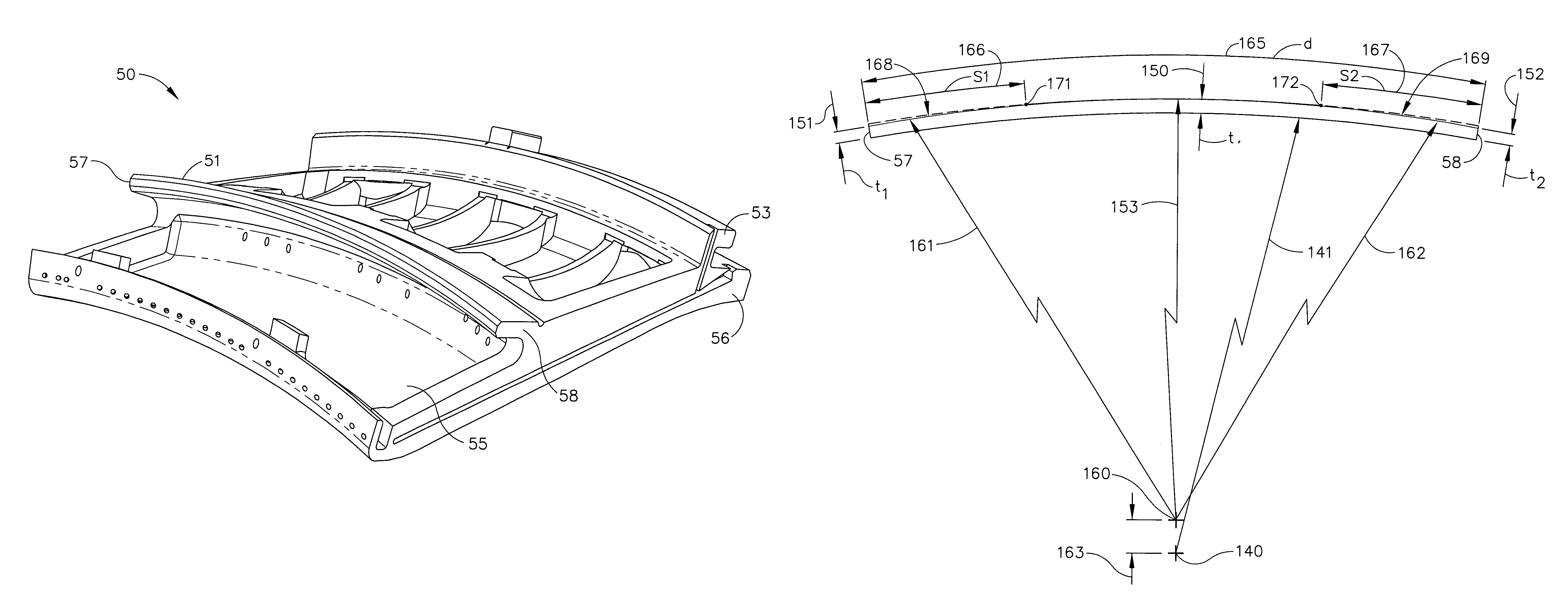
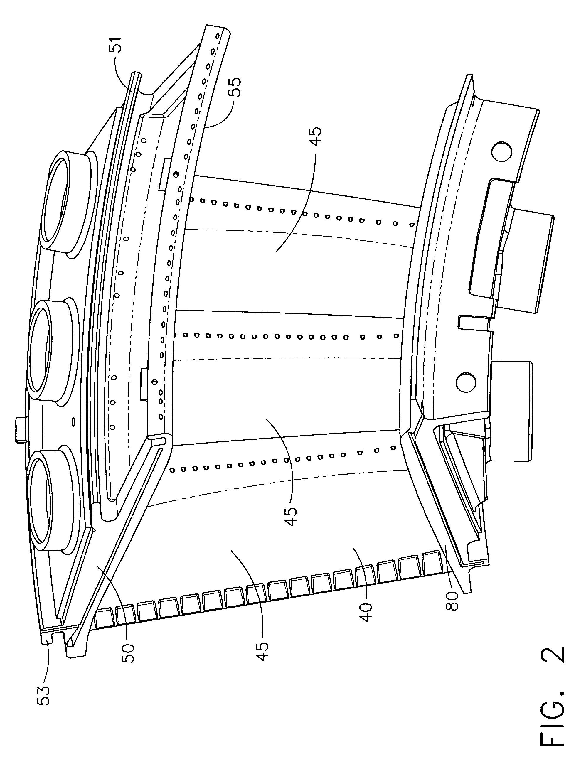
[0017]As shown in FIG. 2 the turbine nozzle segment 40 comprises an inner band 80, and outer band 50 and vanes 45 that extend between the inner band and the outer band. The turbine nozzle segments 40 are usually have multi vane construction, with each nozzle segment comprising multiple vanes 45 attached to an inner band 80 and an outer band 50. The nozzle segment 40 shown in FIG. 2 has three vanes 45 in each segment. The turbine nozzle vanes 45 are sometimes hollow, as shown in FIG. 2, so that cooling air can be circulated through the hollow airfoil. The turbine nozzle segments, when a...


PUM


Abstract

A flange for supporting arcuate components comprising at least one arcuate rail, each arcuate rail having an inner radius, a first taper location, a first taper region, a second taper location, a second taper region, wherein the thickness of at least a portion of the first taper region is tapered and wherein the thickness of at least a portion of the second taper region is tapered.

Description

STATEMENT REGARDING FEDERALLY SPONSORED RESEARCH & DEVELOPMENT[0001]The US Government may have certain rights in this invention pursuant to Contract No. N00019-03-C-0361 awarded by the US Department of the Navy.BACKGROUND OF THE INVENTION[0002]This invention relates generally to improving the durability of gas turbine engine components and, particularly, in reducing the thermal stresses in the turbine engine stator components such as nozzle segments.[0003]In a typical gas turbine engine, air is compressed in a compressor and mixed with fuel and ignited in a combustor for generating hot combustion gases. The gases flow downstream through a high pressure turbine (HPT) having one or more stages including one or more HPT turbine nozzles and rows of HPT rotor blades. The gases then flow to a low pressure turbine (LPT) which typically includes multi-stages with respective LPT turbine nozzles and LPT rotor blades. The HPT and LPT turbine nozzles include a plurality of circumferentially spa...

Claims


Application Information

Patent Timeline
Patent Type & Authority Patents(United States)
IPC IPC(8): F03B3/16
CPCF01D9/041F01D9/047F01D5/147F01D25/243F05D2250/292F05D2250/20
Inventor KAMMEL, RAAFAT A.CHOW, HUMPHREY W.KULYK, MICHAEL PETER
Owner GENERAL ELECTRIC CO
Why Eureka
Try Eureka