In on or Relating to Rotating Machines

a technology of rotating machines and rotating shafts, applied in the field of rotating machines, can solve the problems of impeller failure, affecting the maximum operational life of the impeller, and imposing additional cost on the owner and manufacturer of the turbocharger

Active Publication Date: 2009-11-19
WABTEC UK LTD
View PDF6 Cites 17 Cited by
  • Summary
  • Abstract
  • Description
  • Claims
  • Application Information

AI Technical Summary

Benefits of technology

[0030]It is advantageous if at least the first memory devic...

Problems solved by technology

As pressure ratio requirements increase, so stresses and temperatures on the impellers of turbochargers increase, which can affect the maximum operational lifespan of the impeller.
However, this can result in possible impeller failure if the impeller's life falls short of this figure.
Hence an additional cost is imposed on the turbocharger owner and manufacturer.
This also will have a cost penalty where the impeller, which has been removed, is not yet at the end of its useful life.
However, while this can provide a substantial margin of operational safety, it typically increases the cost of a turbocharger by 30%, which is clearly undesirable.
In some situations the prob...

Method used


Image

  • In on or Relating to Rotating Machines
  • In on or Relating to Rotating Machines
  • In on or Relating to Rotating Machines

Examples


first embodiment

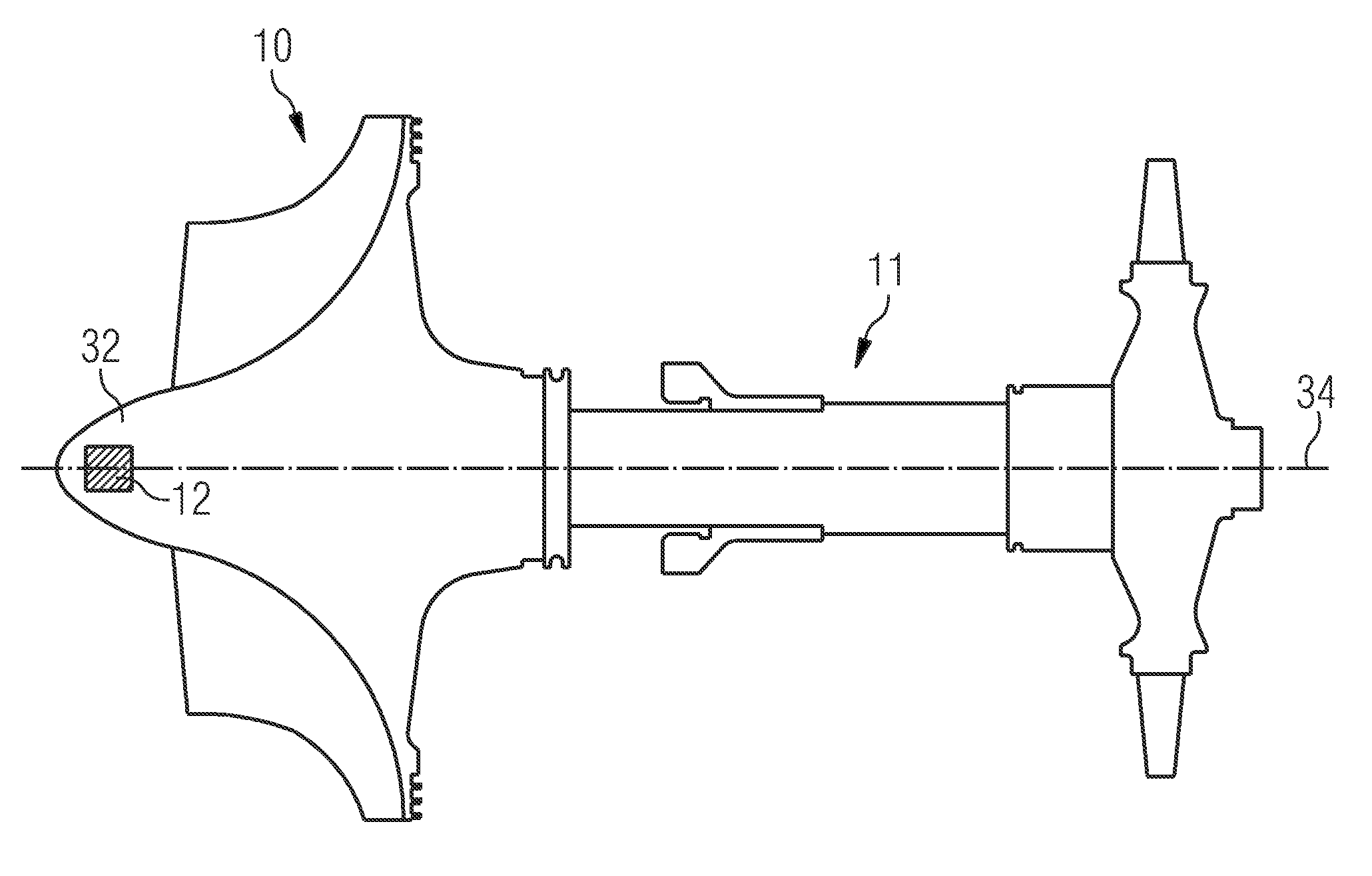
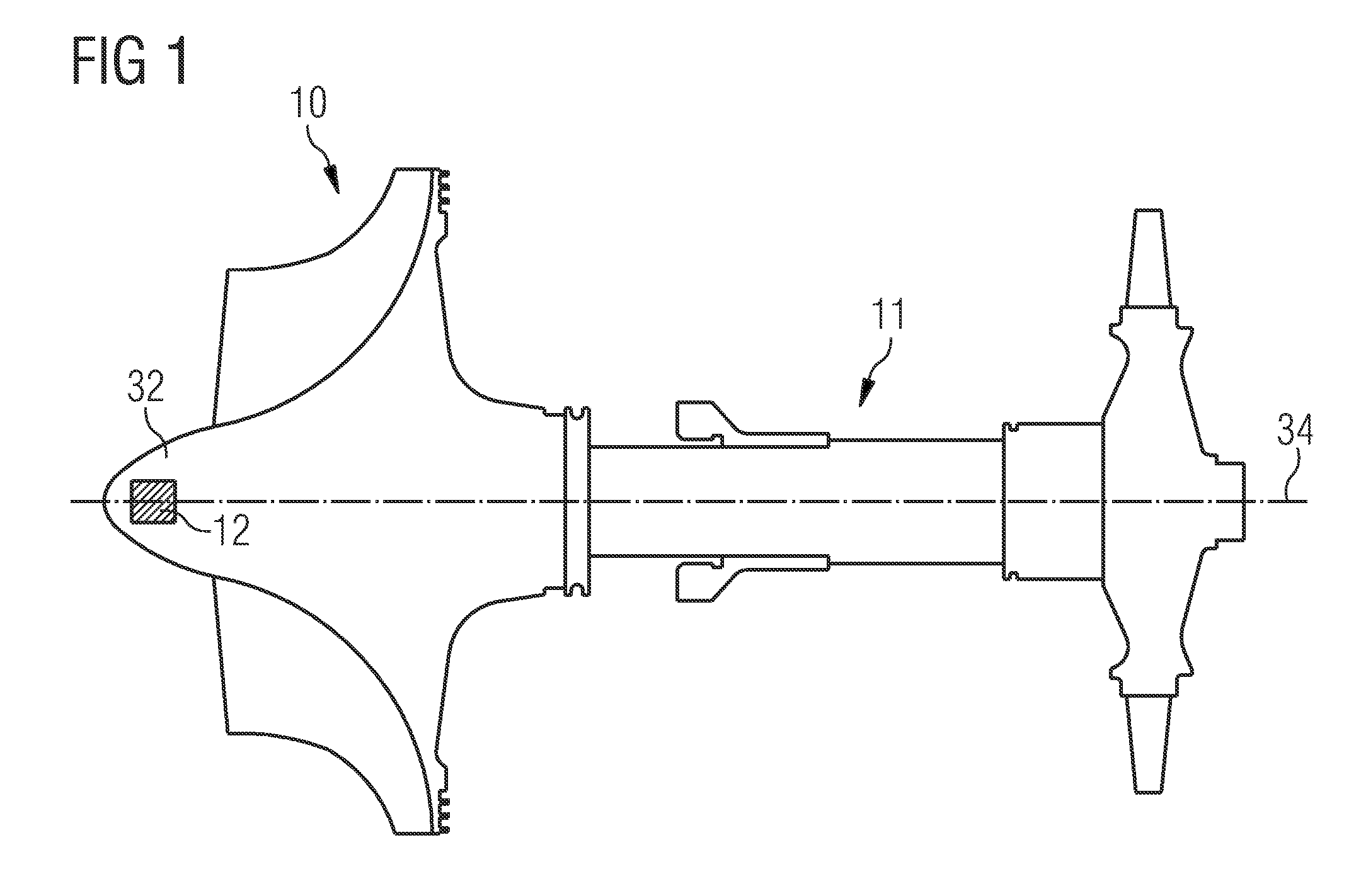
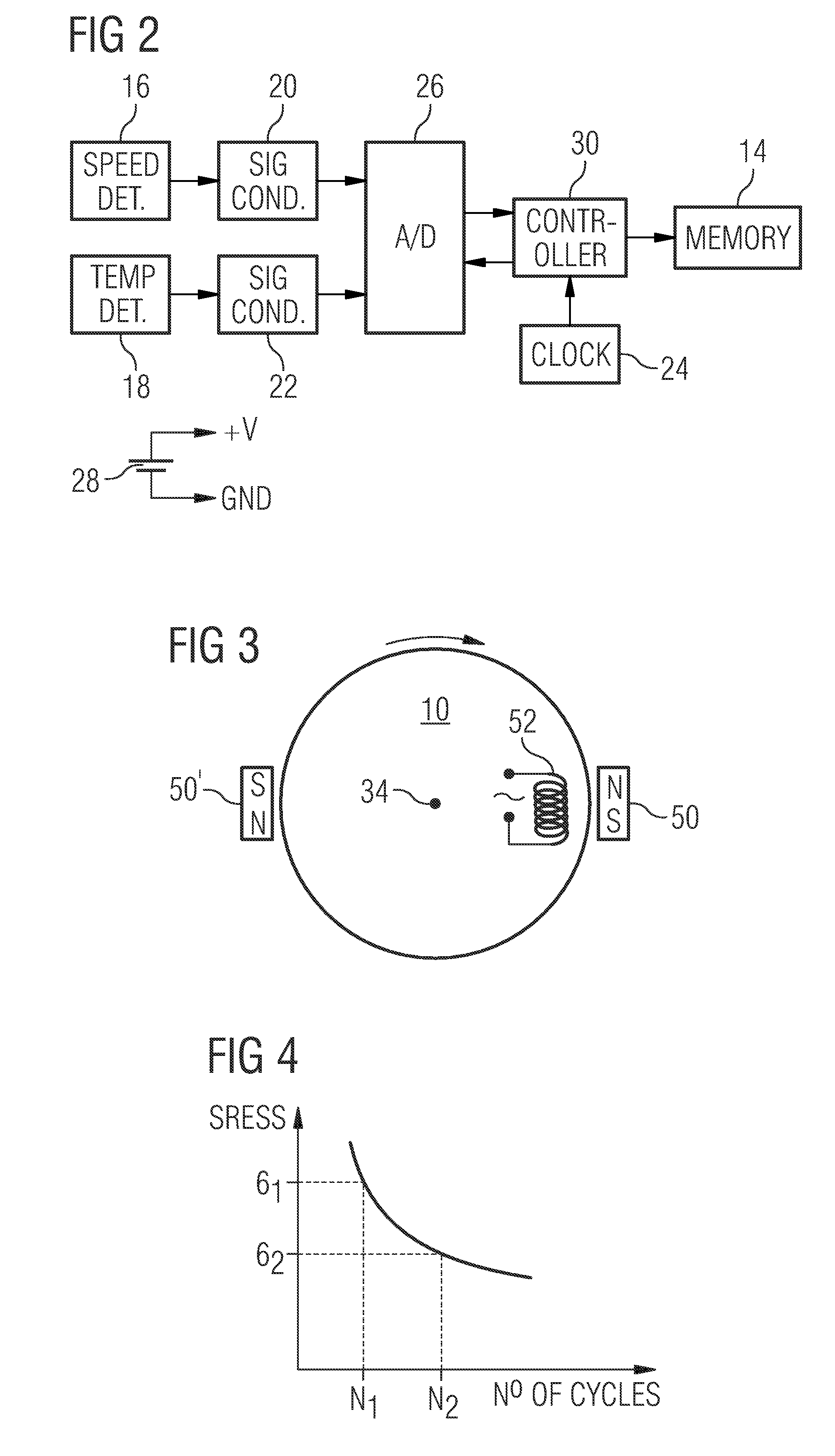
[0052]an impeller in accordance with the invention is illustrated in FIGS. 1 and 2. The impeller 10, which is part of a rotor 11, contains a datalogging device 12, which comprises a memory 14 for storing data relating to the rotational speed and data relating to either the ambient temperature of the air incident on the impeller or the local temperature of the impeller itself. Along with the memory 14 there is included a detector 16 for detecting the rotational speed, a detector 18 for detecting the temperature of the impeller (or ambient temperature), signal conditioning stages 20, 22 for squaring up the waveforms output by the detectors, a source 24 of clock signals, an analogue-to-digital converter 26, a controller 30 for co-ordinating the various operations of the device, and a battery 28 with sufficient capacity to power the various components between services (typically every 2 years). In use, the A / D converter 26 samples the outputs of the speed and temperature detectors seque...

second embodiment

[0080]the invention is illustrated in FIG. 7. In this embodiment the impeller once again houses a memory for storing data, but the speed and temperature detection functions are performed outside the impeller by a speed detector 60 and a temperature detector 62 accommodated in appropriate parts of the turbocharger housing. In the illustrated example the speed detector, which is an inductive HF probe, is located near the nose-end of the impeller, while the temperature detector, which is a thermocouple, is situated at the air-intake end of the turbocharger.

[0081]The outputs of the two detectors 60, 62 are fed to an evaluation unit 64. The unit 64 comprises an antenna 66, by means of which it can communicate with a corresponding antenna 68, which is part of an RF transponder or “tag” located at the nose-end of the impeller 10 along with the memory (not shown) mentioned in connection with the first embodiment. The tag is of a type known per se and preferably operates in the GHz range. RF...


PUM


Abstract

A rotating machine, has a rotary component, which includes a memory device for storing data relating to the past use of the component. The data are associated with rotational speed and ambient temperature, which are detected by detectors either on or off the rotary component. The stored data may be the raw temperature and speed data as sampled over time, which are then used to derive values of low-cycle fatigue and creep damage. These fatigue and creep values are, in turn, correlated with the load profiles of the component to arrive at a value of elapsed lifespan for the component. Alternatively, the stored data may be the fatigue and creep values and/or, preferably, values of elapsed and remaining lifespan of the component. In a second embodiment the detectors are located on the machine casing along with an evaluation unit.

Description

CROSS REFERENCE TO RELATED APPLICATIONS[0001]This application is the US National Stage of International Application No. PCT / EP2006 / 064171, filed Jul. 13, 2006 and claims the benefit thereof. The International Application claims the benefits of British application No. 0515773.0 filed Jul. 30, 2005, both of the applications are incorporated by reference herein in their entirety.FIELD OF INVENTION[0002]The invention relates to a rotating machine including a rotary component, and to a rotating machine which is a turbomachine in which the rotary component is an impeller. The invention also relates to the rotary component itself.BACKGROUND OF THE INVENTION[0003]Turbomachines are in common use in a Diesel-engine environment. Diesel engines are found to require ever increasing turbocharger pressure ratios. Indeed, it has been estimated that every 10 years or so an increase of 0.75 bar is called for, largely as a result of increasingly stringent emissions regulations. As pressure ratio requi...

Claims


Application Information

Patent Timeline
IPC IPC(8): G01K1/20G01P3/44G07C3/00
CPCG07C3/00F04D27/001F05D2260/821
Inventor BROWN, JAMESHEYES, FRANCISNILSSON, ULFWILSON, STEPHEN
Owner WABTEC UK LTD
Why Eureka
Try Eureka