

Apparatus and Method for Providing an Output Signal Indicative of a Speed of Rotation and a Direction of Rotation as a Ferromagnetic Object
- Summary
- Abstract
- Description
- Claims
- Application Information
AI Technical Summary
Benefits of technology
Problems solved by technology
Method used
Image

Examples
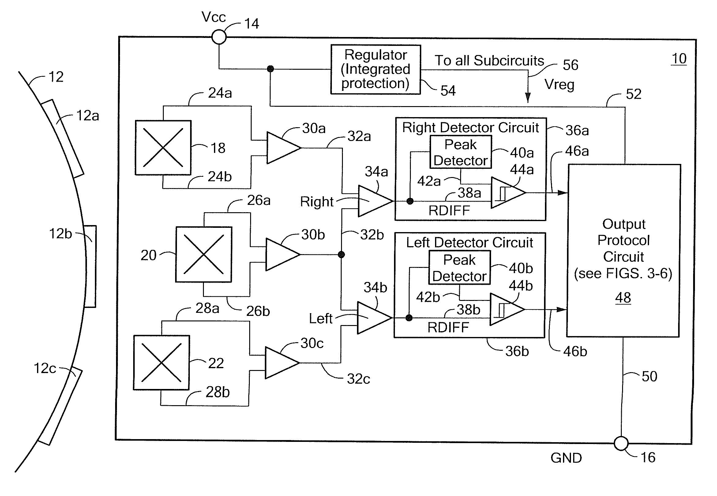
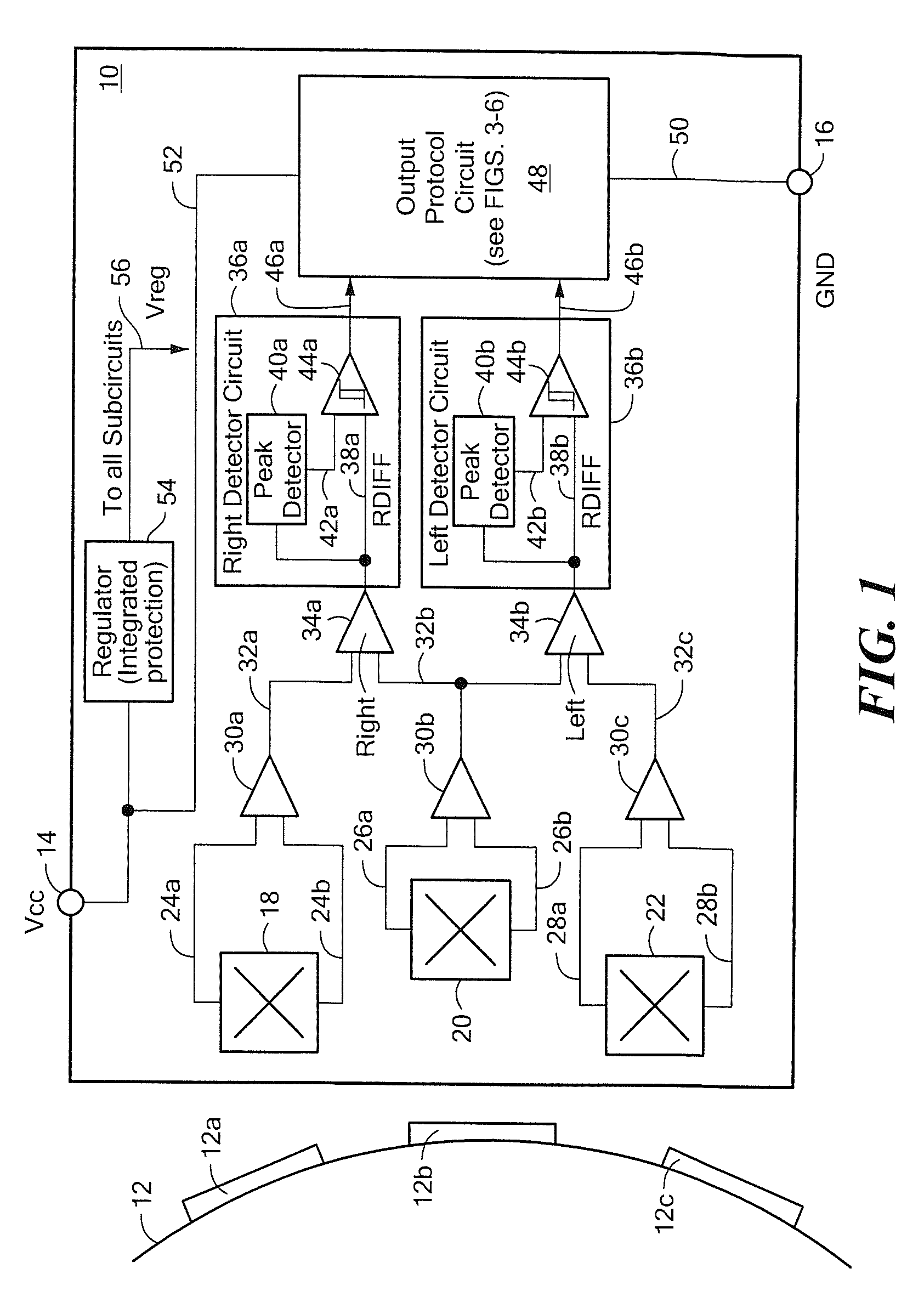
first embodiment
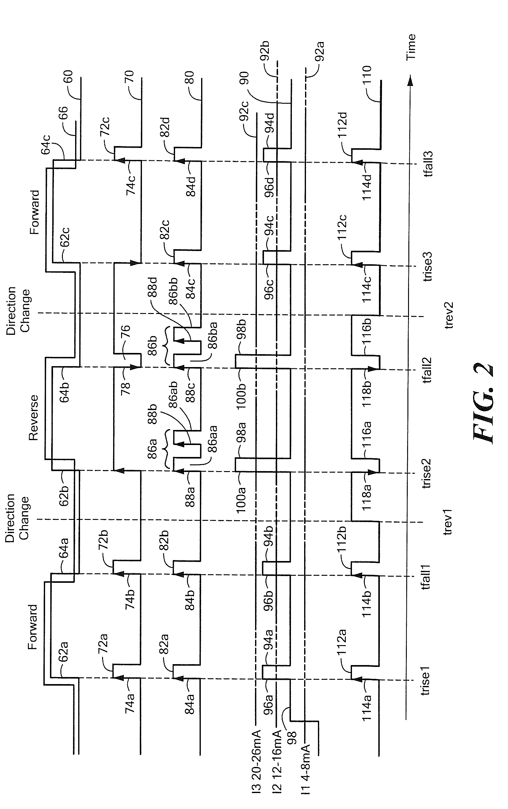
[0039]A curve 70 is representative of the output signal 52 generated by the output protocol circuit 48 of FIG. 1, which embodiment is further described below in conjunction with FIG. 3. The output signal 70 has pulses 72a-72c and 76. The pulses 72a-72c have rising leading edges 74a-74c. The pulse 76 has a falling leading edge 78. It will be understood that the output signal 70 has a plurality of pulses, each one of the plurality of pulses having a leading edge with a transition direction indicative of the direction of rotation. Thus, between times trev1 and trev2, the leading edge of the pulse 76 is a falling leading edge and at other times, the leading edges of the pulses 72a-72c are rising leading edges. However, pulses with the opposite leading edge directions are also possible.
[0040]As used herein, the term “pulse” is used to describe a portion of a binary signal, wherein a width of the pulse is less than about fifty percent of a period of the binary signal. Therefore, it will b...
second embodiment
[0043]A curve 80 is representative of the output signal 52 generated by the output protocol circuit 48 of FIG. 1, which embodiment is further described below in conjunction with FIG. 4. The output signal 80 has pulses 82a-82d, each of which is referred to herein as an “instance” having one pulse. The output signal 80 also has pulses 86aa, 86ab, 86ba, 86bb, which appear in double pulse groups 86a, 86b, and each double pulse group 86a, 86b is referred to here as an instance having two pulses. All of the pulses 82a-82d, 86aa, 86ab, 86ba, 86bb have rising leading edges 84a-84d, 88a-88d, respectively. It will be understood that the output signal 80 has a first number of pulses (i.e. one pulse, e.g., the pulse 82a) occurring in instances (e.g., 82a, 82b) of the first number of pulses when the ferromagnetic object (e.g., gear 12 of FIG. 1) is rotating in a first direction, and a second different number of pulses (i.e., two pulses, e.g., the pulses 86aa, 86ab) occurring in instances (e.g., ...
third embodiment
[0046]A curve 90 is representative of the output signal 52 generated by the output protocol circuit 48 of FIG. 1, which embodiment is further described below in conjunction with FIG. 5. The curve 90 is shown in conjunction with a vertical amplitude scale of signal currents represented by lines 92a, 92b, 92c. The line 92a is indicative of a signal current of about four to eight milliamps, the line 92b is indicative of a signal current of about twelve to sixteen milliamps, and the line 92c is indicative of a signal current of about twenty to twenty-six milliamps. It should be appreciated that the indicated current ranges are illustrative only and that other current ranges can be used.
[0047]The output signal 90 has pulses 94a-94d with a first amplitude between currents represented by the lines 92b and 92c. The output signal 90 also has pulses 98a, 98b with a second different amplitude above a current represented by the line 92c. All of the pulses 94a-94d, 98a, 98b have rising leading e...
PUM
 Abstract
Description
Claims
Application Information