Bearing life determination device

a technology of life determination and bearing, which is applied in the direction of plug gauges, instruments, using mechanical means, etc., can solve the problems of reducing the operation accuracy of the machine, reducing the machining accuracy, and affecting the wear resistance of the bearing that supports the shaft rotated by the motor or the lik

Inactive Publication Date: 2015-02-19
FANUC CORP
View PDF9 Cites 89 Cited by
  • Summary
  • Abstract
  • Description
  • Claims
  • Application Information

AI Technical Summary

Benefits of technology

[0012]The temperature of the bearing may vary depending on the rotational speed of the rotation axis supported by the bearing, and the degree of influence on the bearing life per revolution may vary depending on the temperature. In this arrangement, however, an integrated corrected rotation amount is obtained by converting the rotation amount at each rotational speed for correction to an amount based on each unit revo

Problems solved by technology

In various machinery, such as machine tools and robots, bearings that support shafts rotated by motors or the like are subject to degradation such as wear.
If the bearings are degraded, the operation accuracy of the machinery is reduced.
In the case of a machine tool, its machining accuracy is reduced.
Since those bearings which support r

Method used


Image

  • Bearing life determination device
  • Bearing life determination device
  • Bearing life determination device

Examples


first embodiment

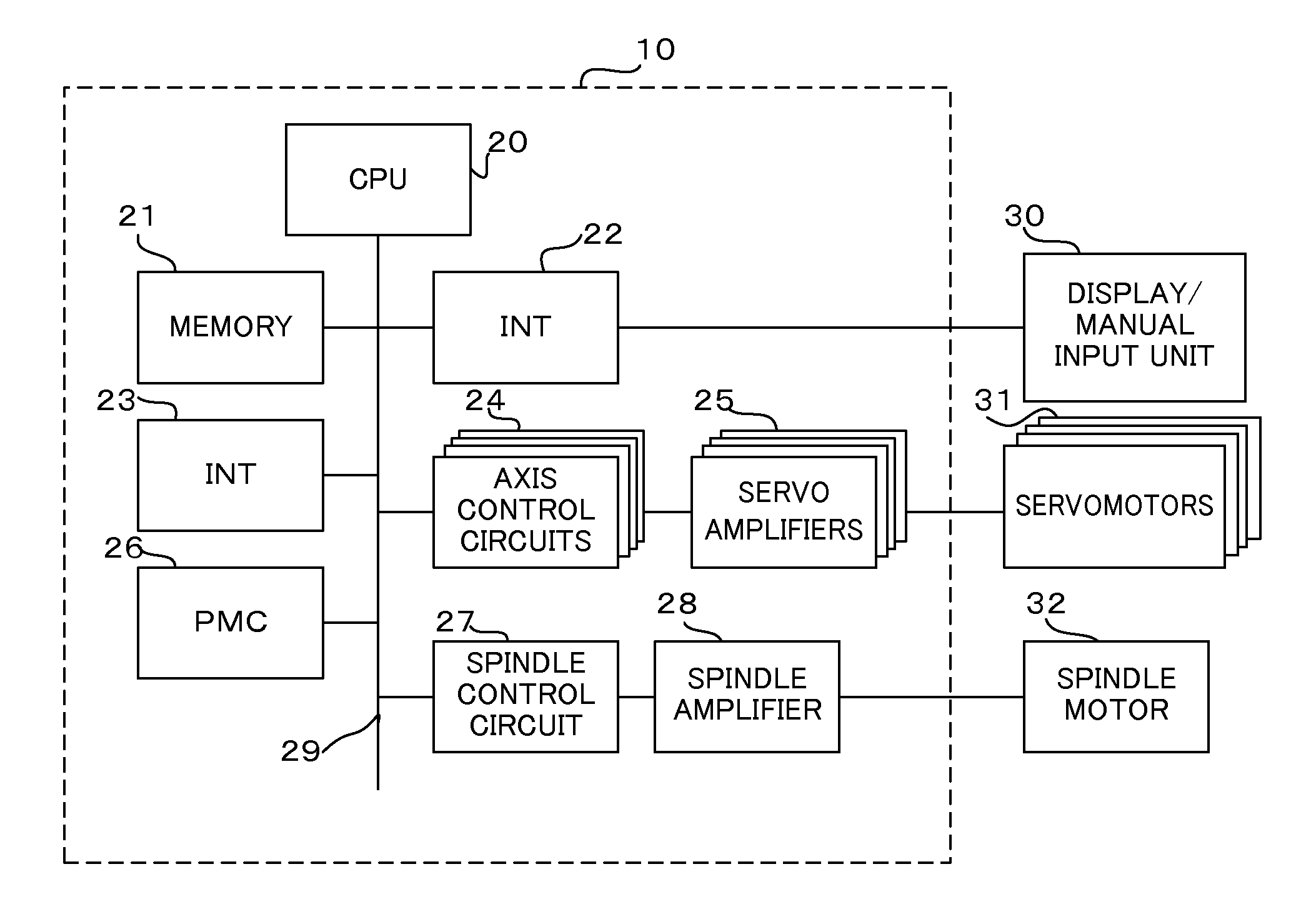
[0022]FIG. 1 is a schematic block diagram of a control device for a machine furnished with a bearing life determination device according to a first embodiment. In this first embodiment, the machine is a machine tool, and the control device for controlling the machine is a numerical control device. FIG. 1 is a schematic block diagram of the numerical control device 10. In the first embodiment, moreover, the life of the spindle of the machine tool, which is worked hard, is determined.

[0023]A CPU 20 is a processor for generally controlling the numerical control device 10 and is connected to a memory 21, interfaces 22 and 23, axis control circuits 24, programmable machine controller (PMC) 26, and spindle control circuit 27 by a bus 29.

[0024]The CPU 20 reads a system program stored in a ROM in the memory 21 through the bus 29 and controls the entire numerical control device 10 according to the read system program. The memory 21 comprises the ROM, a RAM, a nonvolatile memory, etc. The ROM...

second embodiment

[0041]According to a second embodiment, the life performance of all bearings or a plurality of selected bearings in a machine is determined. Also in this second embodiment, the machine is a machine tool, and its control device is a numerical control device, such as that shown in FIG. 1. The machine tool has four rotation axes, including a spindle axis and feed axes, that is, X-, Y-, and Z-axes. The spindle axis is driven by a spindle motor 32, which is driven by a spindle control circuit 27 and a spindle amplifier 28. Further, the feed axes or the X-, Y-, and Z-axes are driven by servomotors 31 that are driven by their corresponding axis control circuits 24 and servo amplifiers.

[0042]On receiving a spindle rotation command speed from a CPU 20, as described above in connection with the first embodiment, the spindle control circuit 27 feedback-controls the speed of the spindle motor 32 to be equal to the command speed. On receiving speed commands from the CPU 20, moreover, the axis co...


PUM


Abstract

A corrected rotation amount, based on conversion to a rotation amount at a reference rotational speed, is obtained by multiplying a command speed read in each period by a period time and a coefficient value corresponding to the rotational speed. An integrated corrected rotation amount is obtained by integrating the corrected rotation amount. If this integrated corrected rotation amount exceeds a life limit value, the life of a bearing is determined to be exhausted.

Description

BACKGROUND OF THE INVENTION[0001]1. Field of the Invention[0002]The present invention relates to a device for detecting and determining the life of bearings used in machine tools and various other machinery.[0003]2. Description of the Related Art[0004]In various machinery, such as machine tools and robots, bearings that support shafts rotated by motors or the like are subject to degradation such as wear. If the bearings are degraded, the operation accuracy of the machinery is reduced. In the case of a machine tool, its machining accuracy is reduced. Since those bearings which support rapidly rotating shafts are worked hard, in particular, they are quickly degraded and shortened in service life.[0005]To overcome this problem, a troubleshooting method for a speed reducer with a built-in robot has been proposed in which the maintenance level of a bearing (speed reducer) is indicated. In order to check the wear state of the bearing to use it as a criterion for the maintenance of the bea...

Claims


Application Information

Patent Timeline
IPC IPC(8): G01M13/04
CPCG01M13/04
Inventor MASUYA, MICHI
Owner FANUC CORP
Why Eureka
Try Eureka