Treatment apparatus and treatment device for surgical treatments using ultrasonic vibration

a treatment device and ultrasonic technology, applied in the field of ultrasonic treatment devices and ultrasonic treatment apparatuses, can solve the problems of affecting the quality of surgical treatment, affecting the effect of surgical treatment, and taking a long time, and achieve the effect of convenient cleaning

Active Publication Date: 2010-09-21
OLYMPUS CORP
View PDF38 Cites 233 Cited by
  • Summary
  • Abstract
  • Description
  • Claims
  • Application Information

AI Technical Summary

Problems solved by technology

For instance, when removing the filths, intruded to between the inner sheath and the outer sheath, it is hard for the brush or the like to be inserted to the narrow space to be brought into direct contact with the filths and, hence, not only it takes a long time but also a need arises for the special cleaning device.
Further, probabilities occur with the occurrence of damage only to the outer sheath due to frequent use of the ultrasonic treatment device.
The reason comes from the fact that the operational main part, the inner sheath, the outer sheath and the operational force transfer member are formed in the substantially integrated fashion and it becomes hard to disassemble these component parts.
Therefore, even if a need arises for replacing only the outer sheath of the main unit, an issue has arisen with an increase in cost for replacement.

Method used


Image

  • Treatment apparatus and treatment device for surgical treatments using ultrasonic vibration
  • Treatment apparatus and treatment device for surgical treatments using ultrasonic vibration
  • Treatment apparatus and treatment device for surgical treatments using ultrasonic vibration

Examples


first embodiment

[0042]Now, a first embodiment is described with reference to FIGS. 1 to 12.

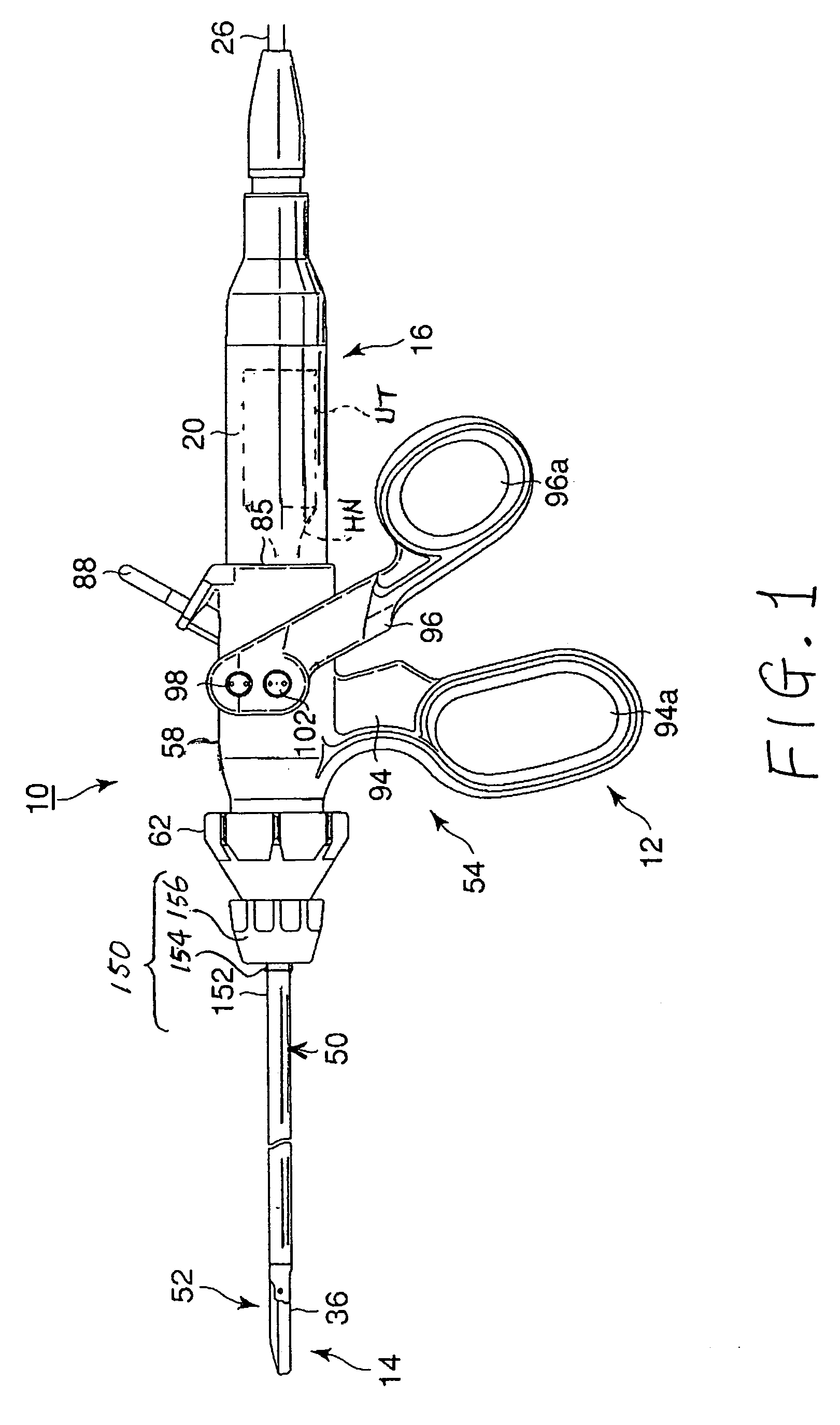
[0043]FIG. 1 shows an ultrasonic treatment device 10 of the first embodiment. The ultrasonic treatment device 10 and an apparatus main part AU form an ultrasonic treatment apparatus US.

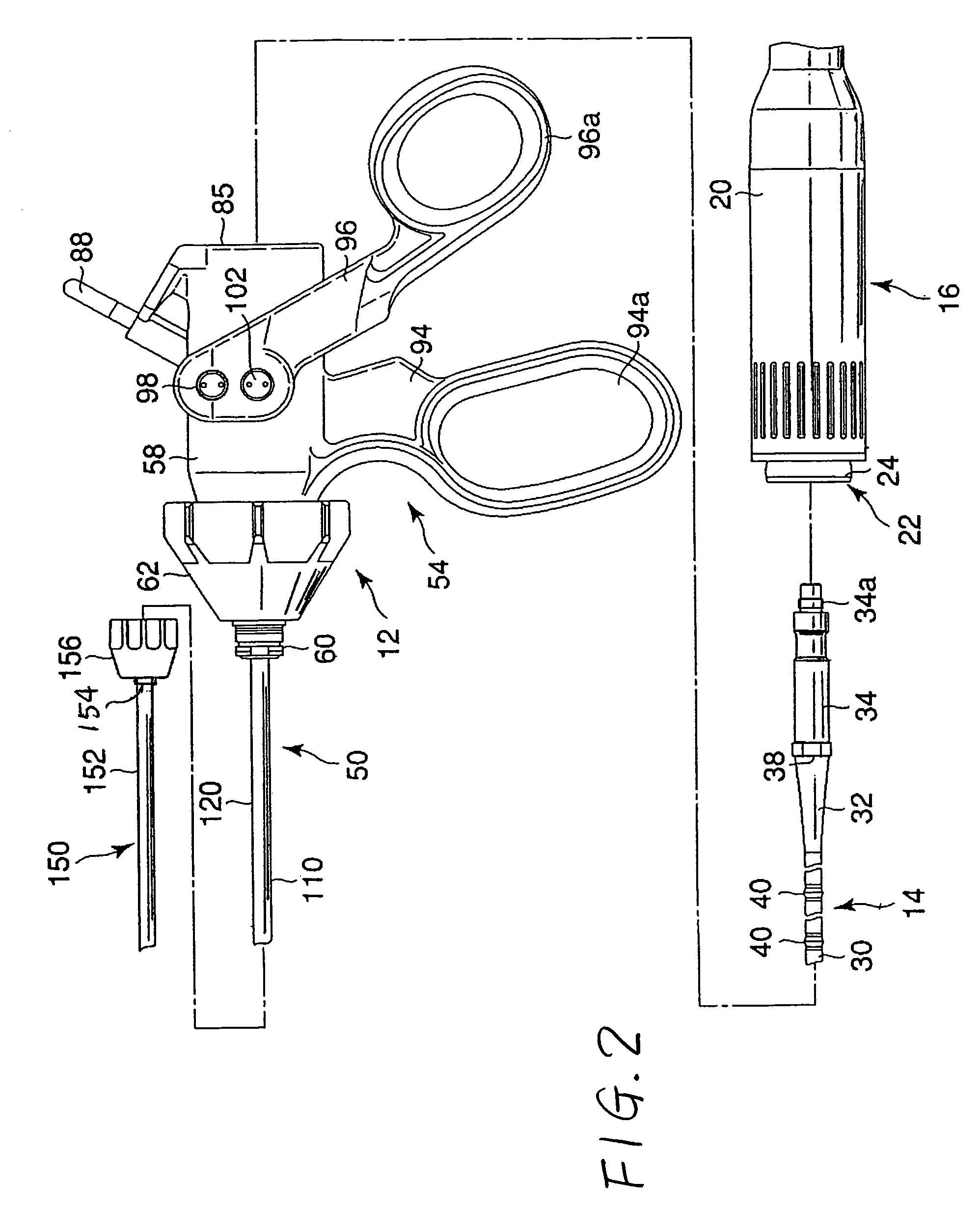
[0044]The ultrasonic treatment device 10, shown in FIG. 1, is comprised of a main unit 12, a probe unit (ultrasonic probe) 14 and a transducer unit 16 as three main units, which are assembled to be detachable from each other. That is, the probe unit 14 is configured in the transducer unit 16 to be detachable therefrom (see FIG. 2). For this reason, a unit, in which the probe unit 14 and the transducer unit 16 are combined, can be detachably mounted to the main unit 12. That is, combining the main unit 12, the probe unit 14 and the transducer unit 16, as shown in FIG. 2, results in an assembly of the ultrasonic treatment device 10 as shown in FIG. 1.

[0045]Also, among the three principal units described above, the main unit 12 in...

second embodiment

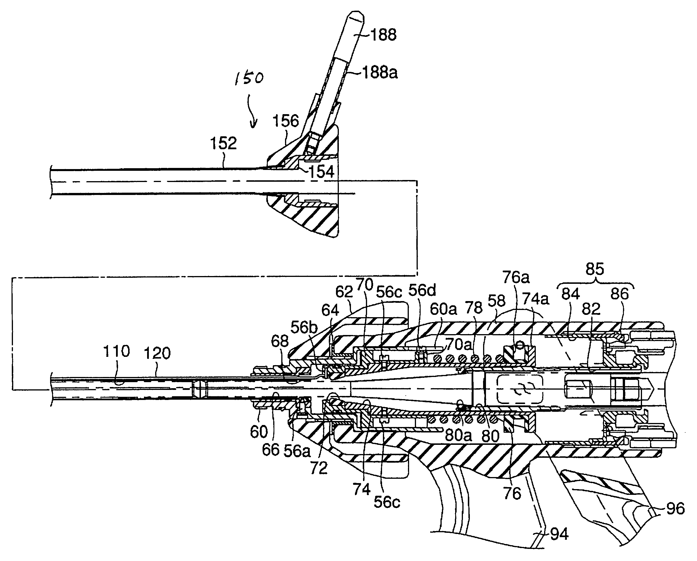
[0112]Next, a second embodiment is described with reference to FIGS. 13 and 14. This embodiment is a modified form of the first embodiment and the same component parts as those of the first embodiment bear like reference numerals to omit detail description.

[0113]As shown in FIG. 13, the high-frequency connector pin 88 is removed from the operational main part 58 of the ultrasonic treatment apparatus 10 of the presently filed embodiment. Instead, a high-frequency connector pin 188 is provided in a connector (electric connector portion) 156 of the outer sheath 150 and covered with an insulative cover 188a. A connector member (electric connector member) 154 of the outer sheath 150 has electrical conductivity.

[0114]Therefore, under a situation where the outer sheath 150 is mounted on the outer peripheral surface of the small diameter portion at the distal end of the rotation-link member 60 of the main unit 12, the high-frequency connector pin 188 is electrically connected to the rubber ...

third embodiment

[0124]Next, a third embodiment is described with reference to FIGS. 15 to 18. This embodiment is a modified form of the first embodiment and the same component parts as those described in the first embodiment bear like reference numerals to omit detailed description.

[0125]As shown in FIG. 15, an ultrasonic treatment apparatus 210 of the presently filed embodiment is comprised of a main unit 212, a probe unit 14 and a transducer unit 16 (see FIG. 16). The main unit 212 further includes a high-frequency sheath unit (outer sheath) 250 that is detachably mounted to the insertion member 50 of the main unit 12.

[0126]The main unit 212 is comprised of an operational main member 258, a sheath connecting member 266, a positioning member 280 and a transducer unit guide 284. The operational main member 258 is formed in a tubular shape with insulation property. The operational main member 258 has a distal end with its inner peripheral surface to which the sheath connecting member 266, to which t...


PUM


Abstract

An ultrasonic treatment device comprises a transducer unit, probe unit, and a main unit. The transducer unit comprises an ultrasonic transducer generating ultrasonic vibration in response to supply of power. The probe unit has a treatment member at a distal end thereof. The probe unit is detachably loaded to the transducer unit, and is equipped with an ultrasonic probe transmitting the ultrasonic vibration to the distal end of the treatment member when the transducer unit is loaded to the probe unit. The main unit is manually grasped by an operator. The probe unit with the transducer unit loaded thereto is detachably loaded to the main unit. The main unit has a cylindrical insert through which the ultrasonic probe is inserted to have the treatment member protruded outwardly when the probe unit is loaded. The main unit further has an outer sheath detachably covering an outer surface of the insert.

Description

CROSS REFERENCE TO RELATED APPLICATION[0001]The present application relates to and incorporates by reference to Japanese Patent Application No. 2004-098229 filed on Mar. 30, 2004.BACKGROUND OF THE INVENTION[0002]1. Technical Field[0003]The present invention relates to an ultrasonic treatment device and an ultrasonic treatment apparatus that are able to generate ultrasonic vibration for enabling treatment on a living tissue using such ultrasonic vibration.[0004]2. Related Art[0005]Now, ultrasonic treatment apparatuses have become a vital requirement as one of medical devices in medical wards for surgeries.[0006]The ultrasonic treatment apparatuses include those of various types as described below. Such examples include one that is known from Japanese Patent Provisional Publication No. 2002-224133. This literature discloses an ultrasonic treatment device in which ultrasonic vibration, generated with an ultrasonic transducer, is transmitted to a probe to allow a treatment member, mount...

Claims


Application Information

Patent Timeline
Patent Type & Authority Patents(United States)
IPC IPC(8): A61B17/32A61B18/18A61B18/00A61B8/00A61B18/14
CPCA61B17/320092A61B18/1445A61B2017/320093A61B2017/320095
Inventor MASUDA, SHINYA
Owner OLYMPUS CORP
Why Eureka
Try Eureka